There are far more than five senses available in the bleak sensorium of human existence, and one of them is the sense that you could’ve done better. Could I have done better? Let’s find out.
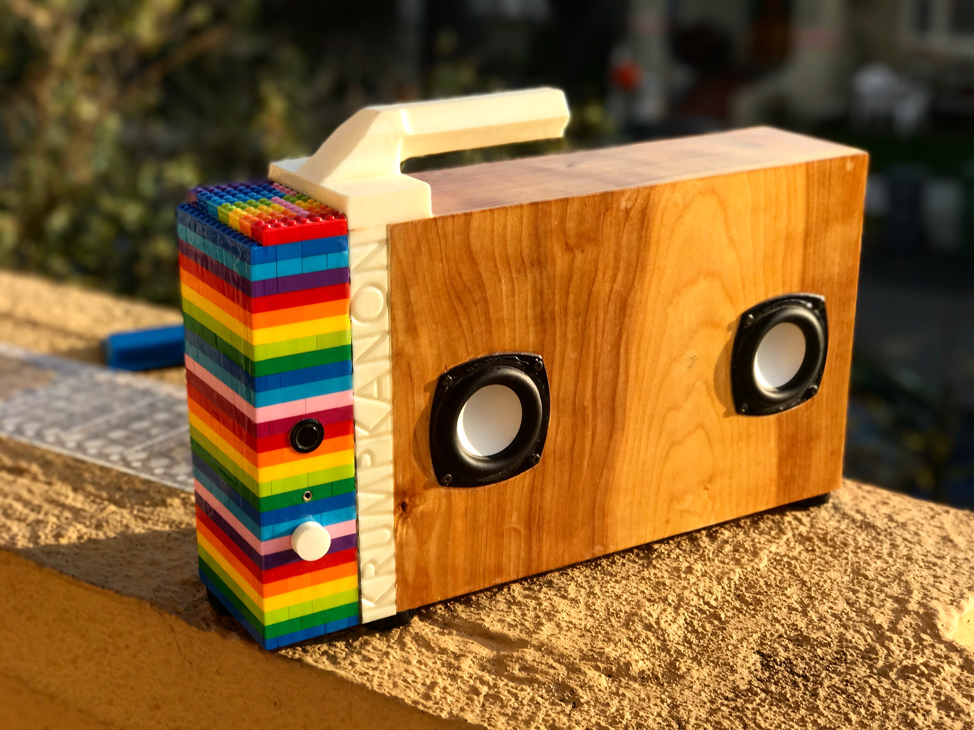
Obligatory finished product first:

I think the journey began confidently over beers, but the tolerances involved in interpreting what someone means by “portable and loud but doesn’t have to be too loud but also make it look really cool” can allow for a lot of design doubt (by no fault of their own–it’s just hard to gauge what reference points people have for “small” and “loud”), and so by the time I packed the Tesselator out, I had built 6 separate designs, each one but the last dusted in a fine sheen of “not-quite-good-enough.” This is their story (dim the lights).
ROUND 1: TOO BIG
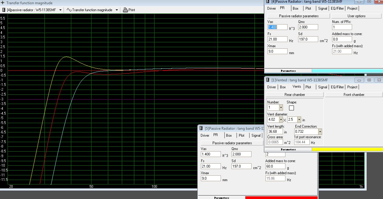
Try 1 was actually pretty awesome. Basically, I wanted to see what the hype was about with the HiVi B4N’s. Ports in small boxes often of chuff me the wrong way and the client wanted “big circles on the front,” which I interpreted to mean speakers. Plus, I go for passive radiators when I can…and so I went for a passive radiator design. I had been having luck with asymmetry, and I wanted to carry a “T” motif through the design.
The problem with the B4N’s that all the fanboys won’t admit is there’s an insanely high Q 15 dB break up mode right at 3kHz, and it likes to jump around depending on boundary conditions, air temperature, zodiac sign, etc. [For the uninitiated, basically the B4N is the classic DIY beginner speaker design because it sounds and looks good, is cheap to make, and because so many other people have built it. However, the all metal cone it’s based around tends to “ring” like a bell at annoying frequencies]. So I wanted to be at least 15 dB down by 3kHz which meant a tweeter that could hit 1.5 kHz, and for directivity reasons, I decided on a 500 Hz crossover, which obviously meant I was going to use the Aurasound NS1s.
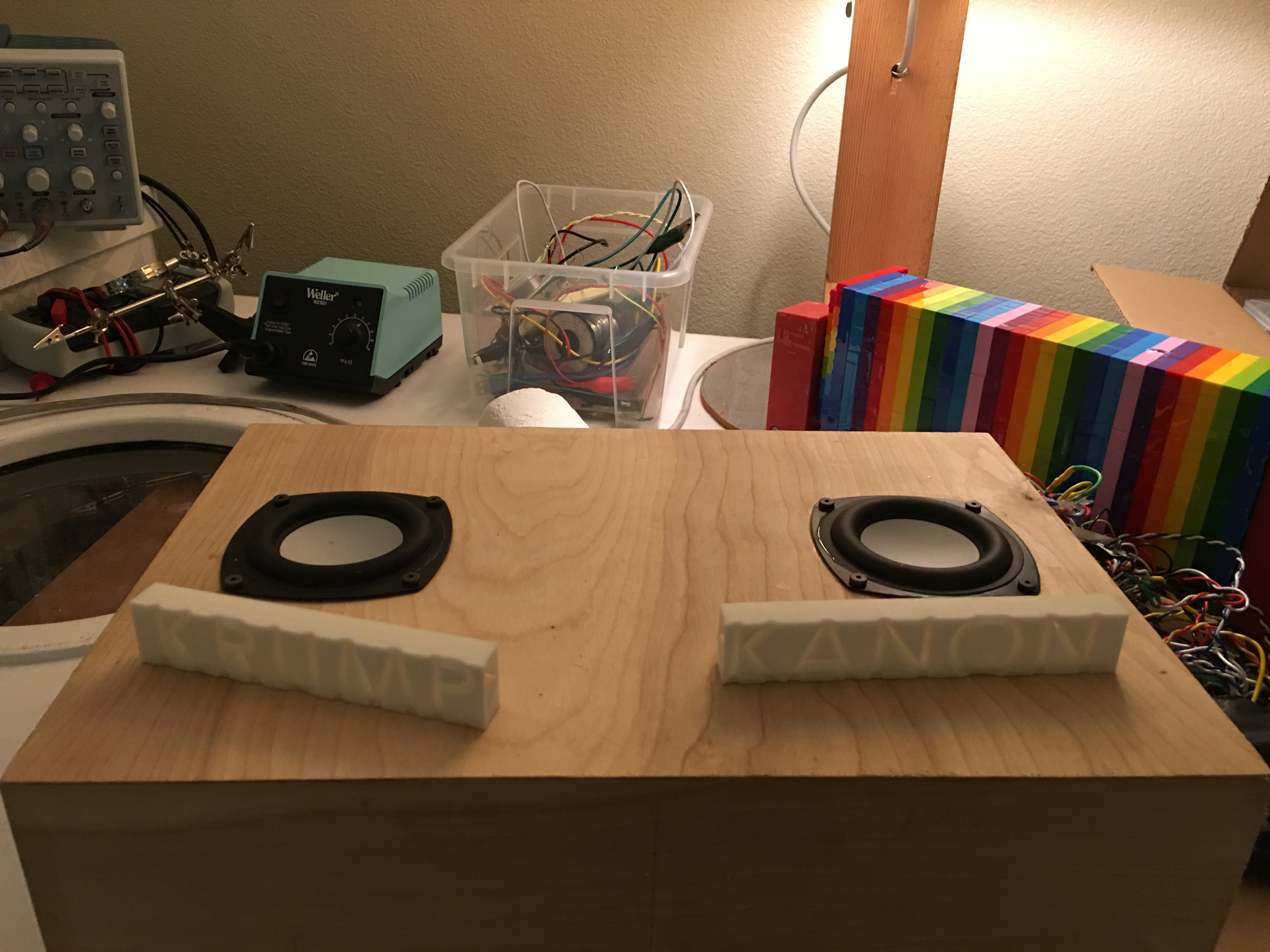
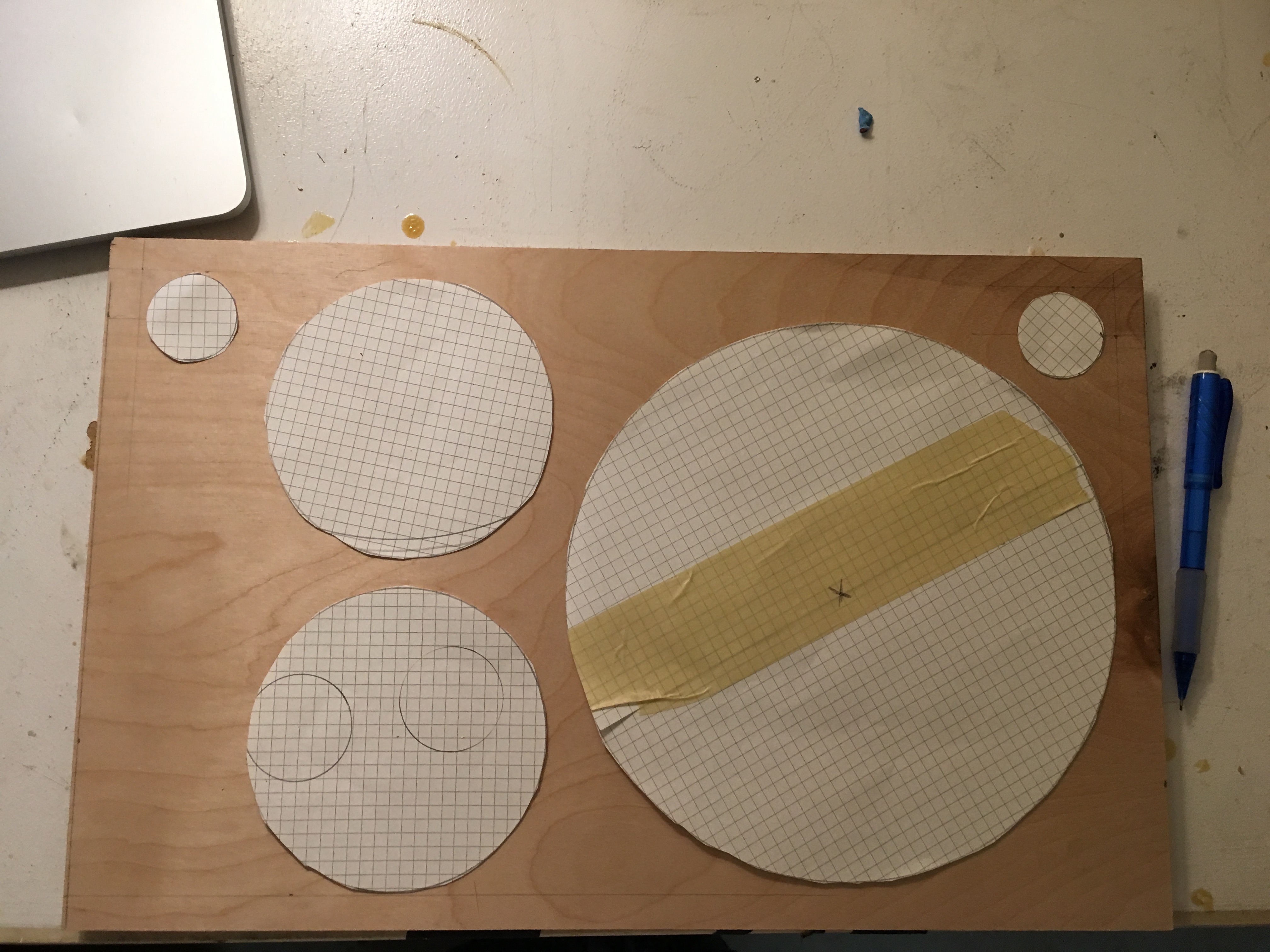
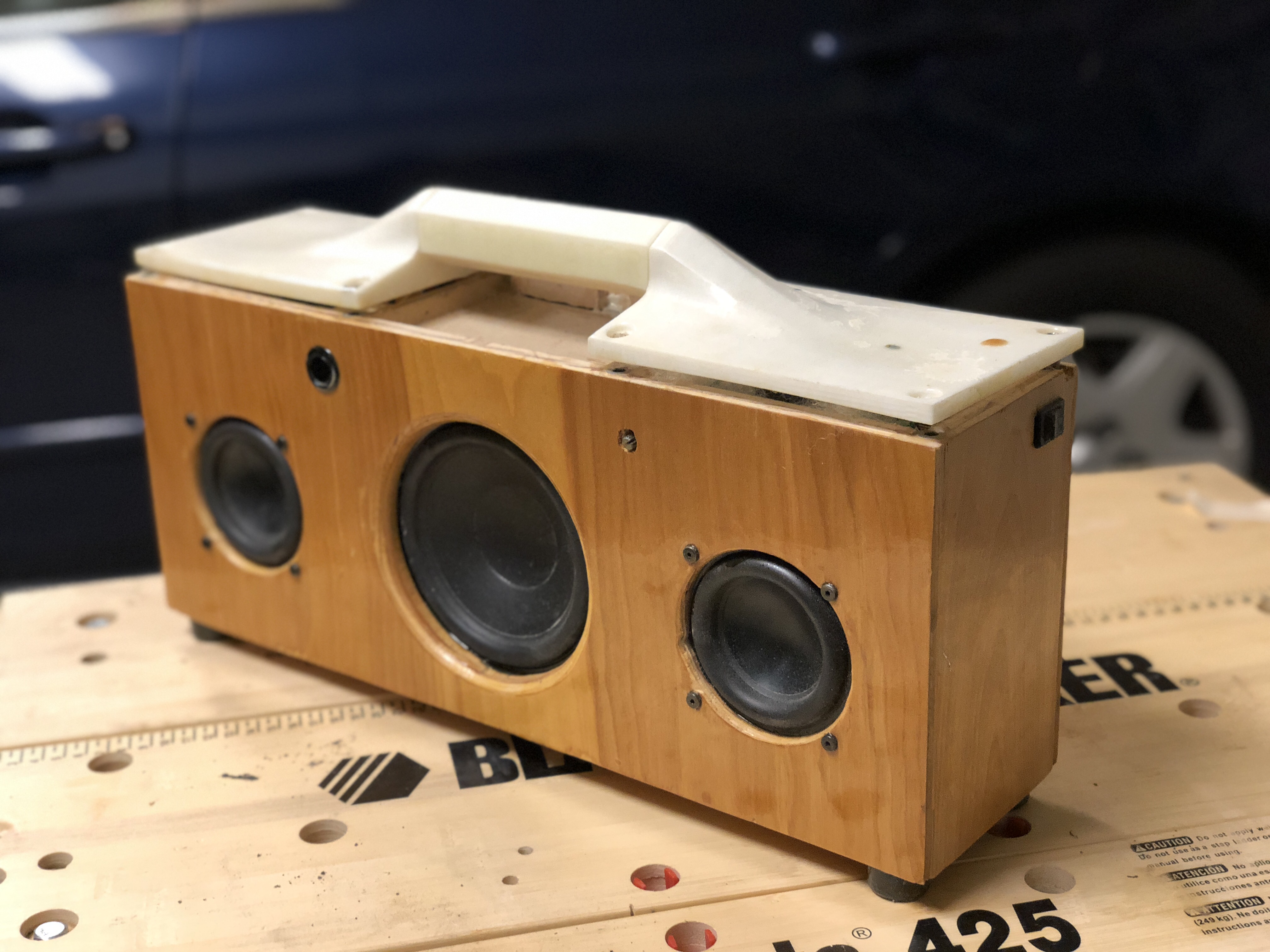
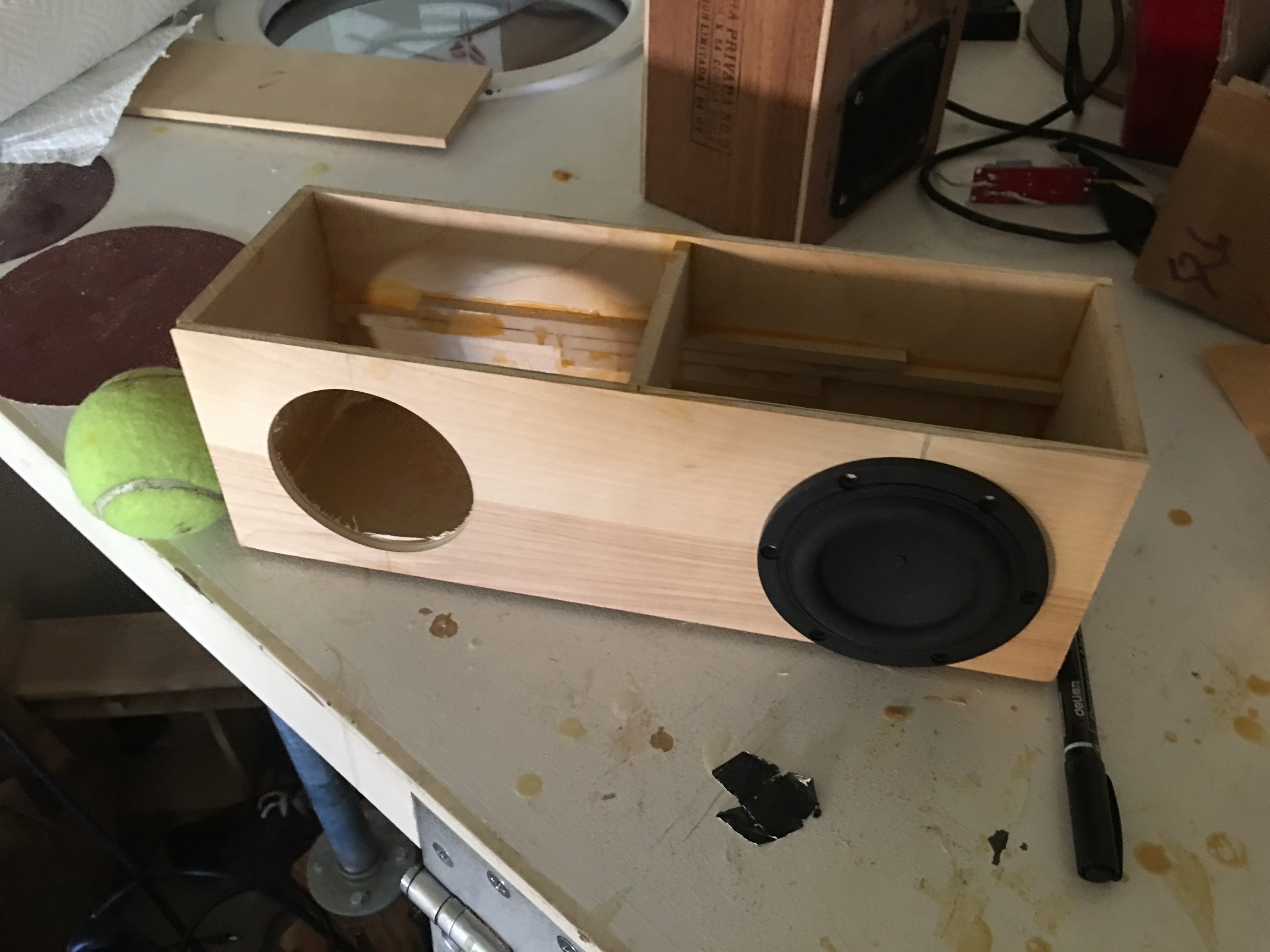
Then I found a sweet spot of plywood that I could waterfall from top to front face to edge, cut with confidence, laid out some paper circles for test fit, and very poorly lock-mitered the shit out of the wood.
Lock miters as promised: The separated volume is for the electronics–lesson learned from previous projects is when trying to attain a good seal, either get better at electrical engineering, or compartmentalize your bad work.
Of course, I still overestimated my abilities and placed the batteries in the acoustic chamber for space reasons. The white boxes are the enclosures for the NS1s.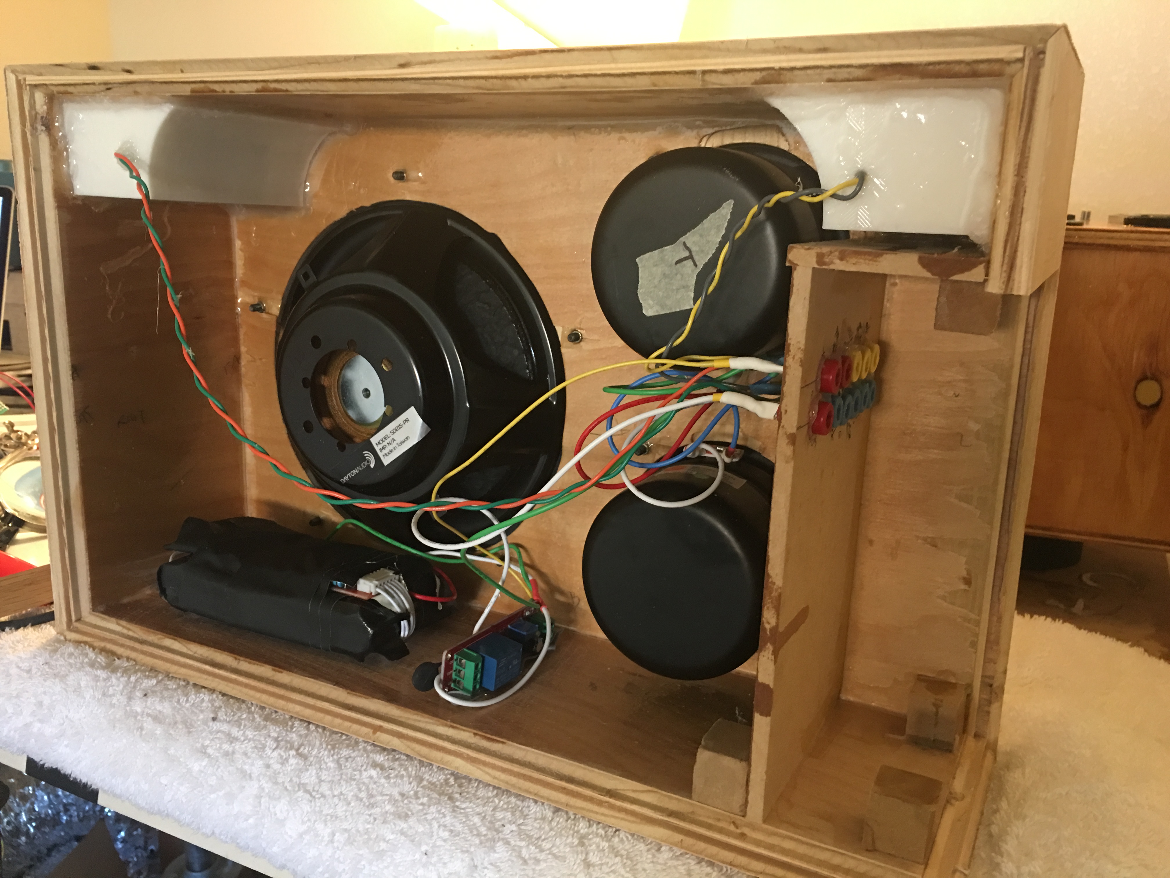
I also had the idiotic notion that using banana plugs as pass-throughs would be simplest, but not only did I get the polarities wrong, it turns out banana plugs are super expensive and take up tons of space: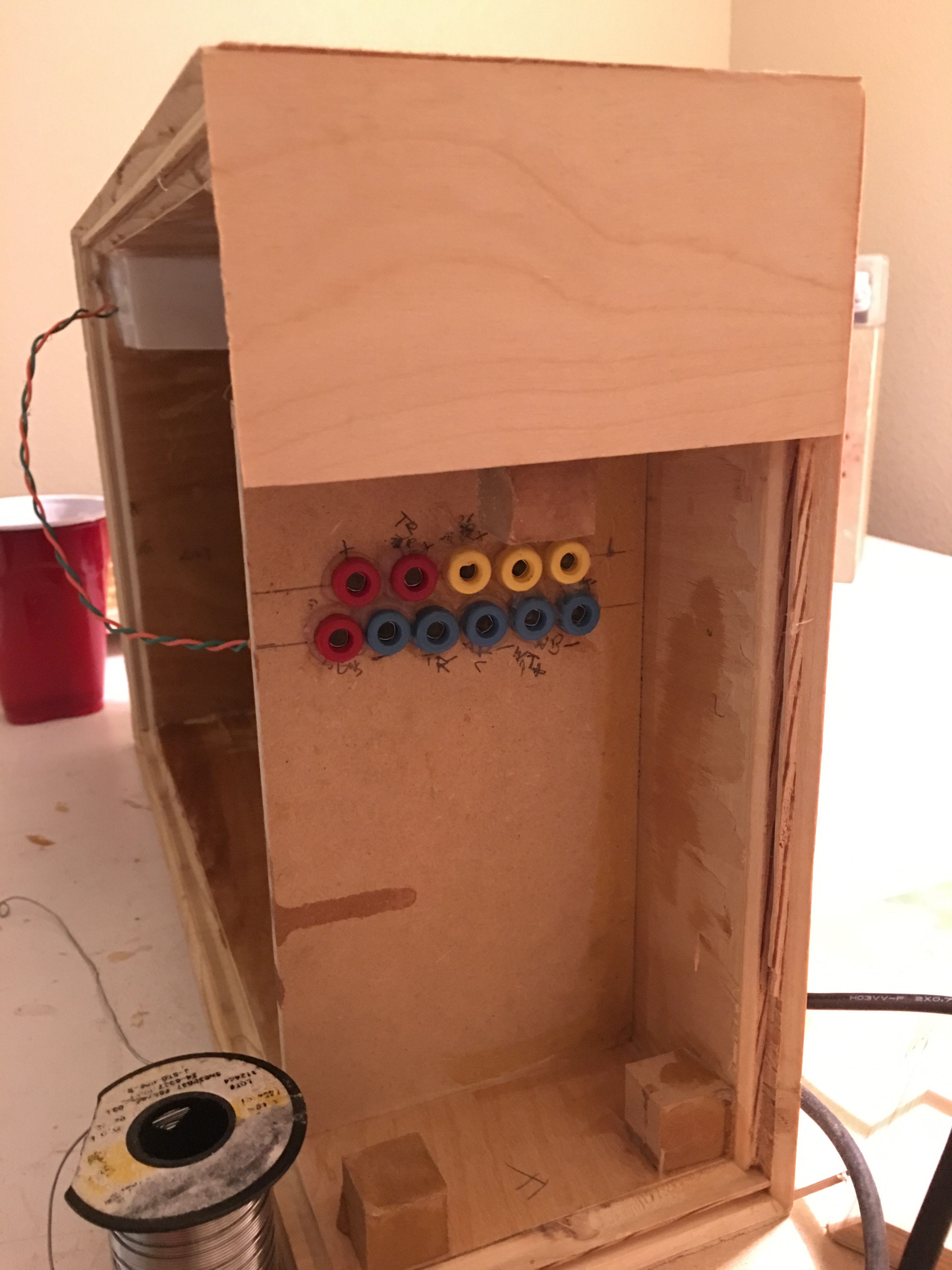
I didn’t manage to fuck up the miters too much and the face is perhaps lovable by more than it’s mother:
I cut out some purple heart and embedded some glow in the dark for the volume knob:

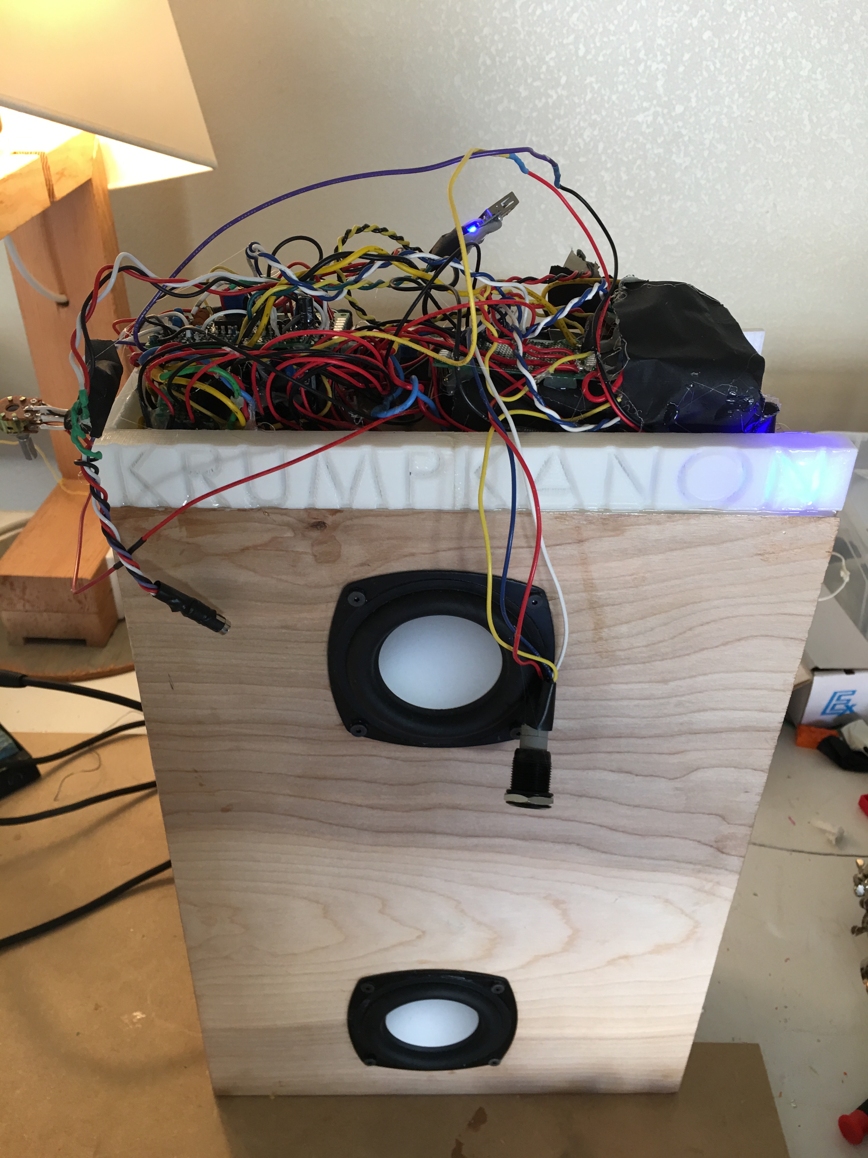
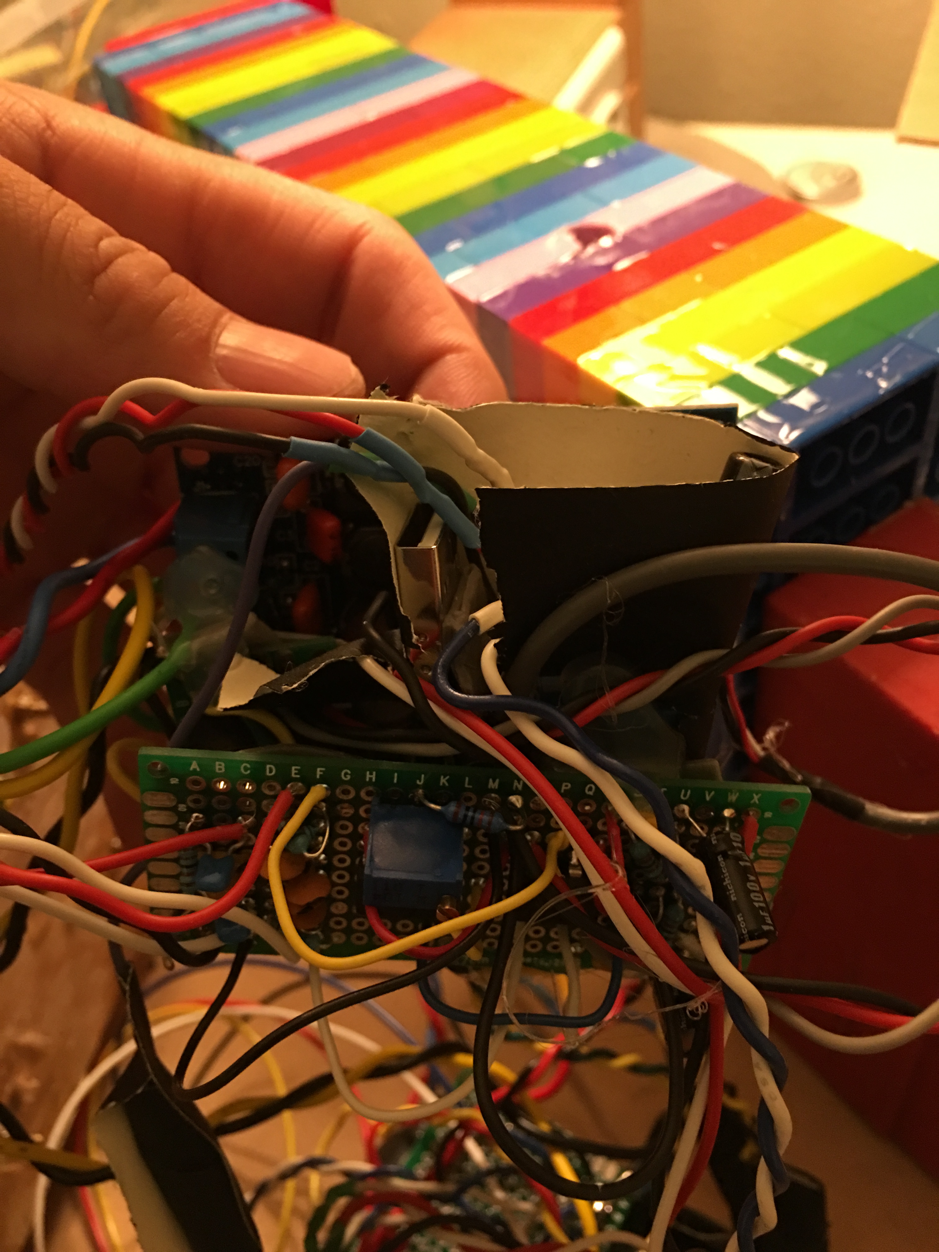
With all that shit sorted, it was time to make an absolute mess of the ASP. The signal chain starts with a power-source isolated bluetooth chip, which is split by an op-amp active crossover, the low frequencies going to a china-market bought TDA7492 class D amp and then to the B4N’s while the high frequencies are padded down by potentiometer and sent to a similarly procured TPA3118D2 amp. The TDA7492 is rated for 40W into 8 ohms @ 25V @10% THD, which works reasonably with the B4N’s 25W RMS rating. Typically it’s better to spec an amp with more headroom (@ less THD) over the continuous power rating of a woofer in order to match the crest factor of music, but I didn’t think of that at the time.
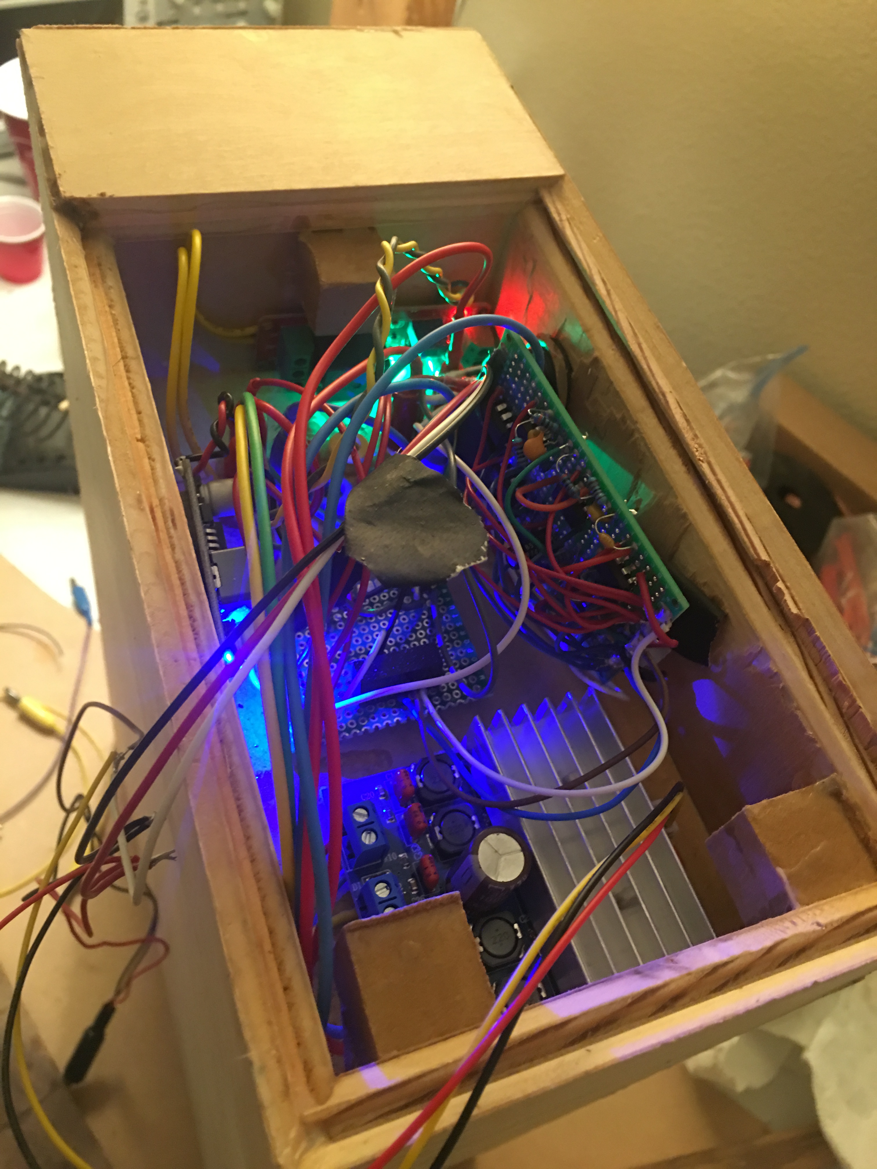
This is the last build I used analog signal processing on, partially because of the above mess of wires. Here’s the terrible wire management in context:
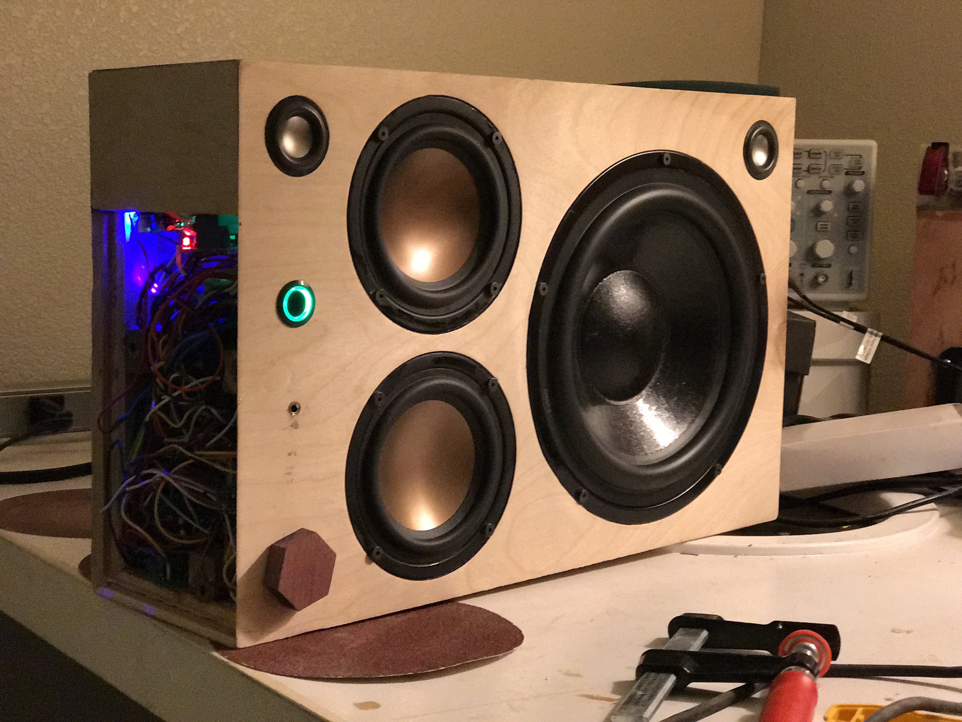
I opted for a glow in the dark, 3D printed, inset handle to preserve the form factor, and then slapped some spar varnish all over that bad boy and called it a day.

ROUND 2: TOO QUIET
Sometimes things come together, and sometimes they come together perfectly. This was not either of those scenarios; the “Tesselator” it’s actually just a decent name pun. Honestly, I was pretty happy with Round 1, but it was just not quite there. It was a little too big, and the lock miter bit I used for the edging was one of those cheap amazon finds that reflect their pricing in their quality. So, I started completely anew…by taking an old project that had been called into half-hearted existence with 3 other siblings in a similarly iterative process that finally yielded the Krump Kanon and cutting it in half. In general, this approach is poor.
It sucked for multiple reasons, some of which were that it was ugly and sounded bad and was still too big. Essentially, it failed to meet any of the criteria laid forth.
ROUND 3: TOO LITTLE BASS
I then tried a new design that was basically Round 1 but with half the stuff in half the space. It also sucked. I was convinced that it wouldn’t because of my experiential lesson on KK Round 2–“efficiency is king”–but it turns out that only works if you have a pleasing natural response or some good DSP.
It was doubly a shame because the wood that went into the box was beautiful, but for some misguided reason, I used the cheap lock miter bit from Round 1 and, completely to my surprise, it didn’t work well the second time either.

ROUND 4: TOO HAMMERED
I then decided that everything I had decided was wrong, that efficiency wasn’t king, and it was all about extension. I went back to some of my “super-compact design” notes and decided to drag some micro-subwoofer Tang Bands into wretched existence. The only problem is that tuning a small box to subwoofer frequencies requires a long-ass tube (because the air spring in a small box is relatively stiff, you need a lot of acoustic mass in the resonating port to get a low resonance frequency), and long-ass ports are very inconvenient to fit into small boxes (not a problem encountered in my daily life). I had a minor stroke of brilliance stroke and decided to make a port that was both a long-ass tube AND a handle, therefore circumnavigating this issue. Here is the relatively tiny box, which looks shitty because I had also come up with the terrible idea that I’d wrap the whole thing in carbon fiber once assembled:
And the incredibly sleek and not at all awkwardly protruding port/handle design. 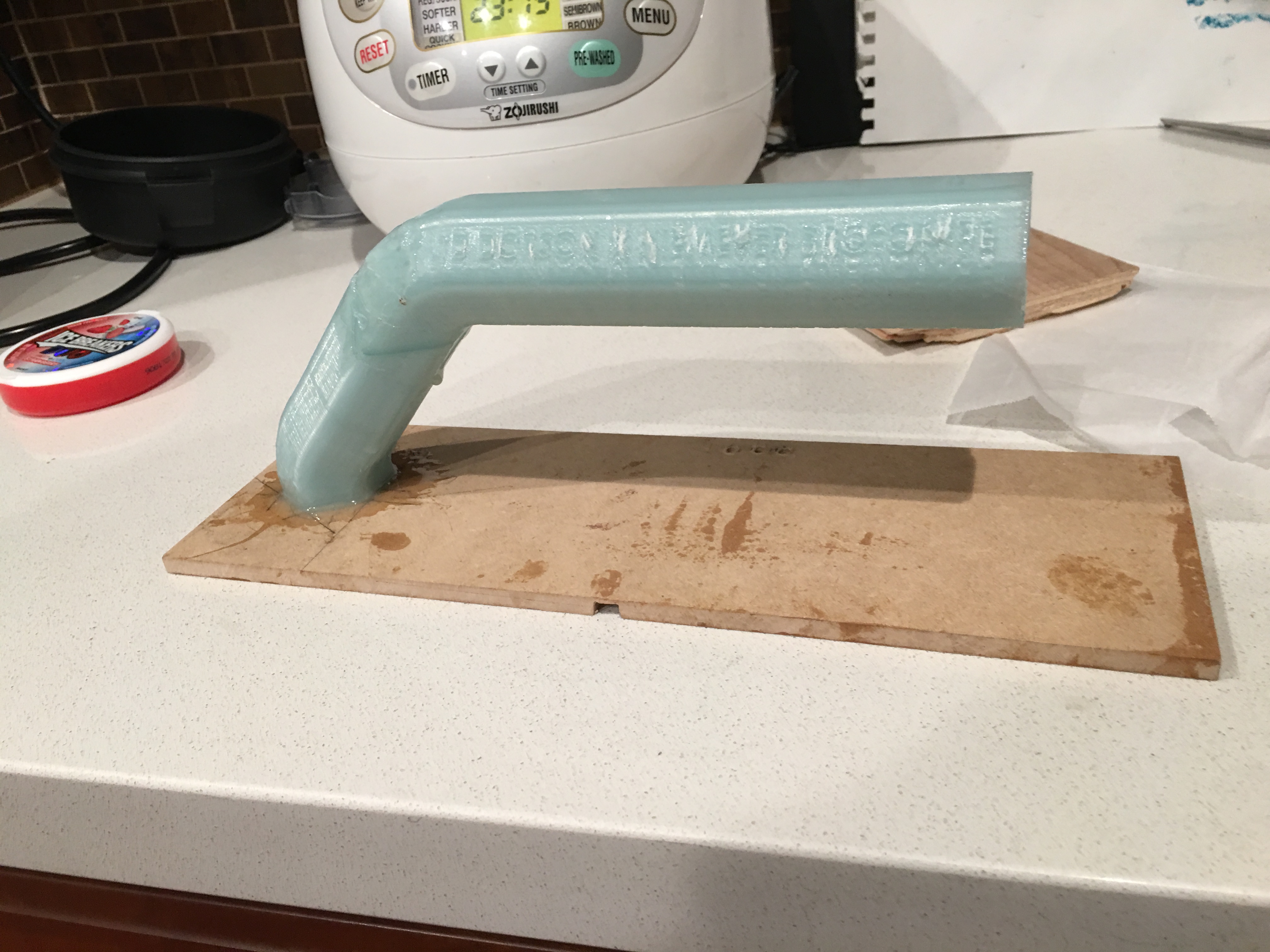
I set the thing up, hit play and was, for the first time in a long time, pleasantly surprised. Here’s a casual video of it in a living room (turn ya sound up and throw on some head phones to appreciate the FIDELITY that’s SPEWING out of this BOOMBOX).
For such a tiny little thing, it was really moving air. It had real potential until I hit it with a hammer.
ROUND 5: TOO UGLY
Not really much to go on about here. It was ugly. I underestimated how weird it would look to have the speakers sticking out of the face instead of flush mounted, and the thing looks like a damn bug-eyed pug.
ROUND 6: NOT BAD
In a surprisingly reflective and narratively satisfying moment, I decided to combine the lessons of the last 5 iterations. I drew up a plan for a small, relatively efficient boombox with precise waterfall miters, inset speakers, DSP, and a port handle. And no fucking carbon fiber.

THE DESIGN
On to the even more boring stuff. Yes, yes, I know the stereo image is going to be ruined by placing the “tweeters” on top of each other. But it looks cool, and there’s no point in attempting to get stereo width out of a box narrower than one’s head.
Anyway, it’s got 2x TB W3-1876 in a mono “sub” configuration, sitting in a 3.7L box stuffed with light polyfill, tuned to 48 Hz with a 12″ long by 1.2″ diameter port. This theoretically gives an f3 of 42 Hz. The port is a 3D printed 3-section design that was epoxied together for surface finish and adhesion. It’s flared on both sides equally for symmetry. The “tweeters” are 1″ W1-1070SH, which are sitting in a 0.1L box and crossed over in a 48 dB/oct LW DSP crossover at 500 Hz. The outer dimensions are approx 4.5″Hx4.5″Dx14″ and the 80Wh battery supplies 24V (nominal) to a China Black Market TDA7492 (to run the woofers) and a CBM TPA3118D2 (for the tweeters) for about 8h of quite listening and 4 hours of TURNT listening MiniDSP 2×4 runs the tuning, and the bluetooth is run by an APT-X Bluetooth 4.0 chip. The advantages of this chip are high quality transmission with surprisingly low radio noise, but by some trick of China-blackmarket circuitry, it manages to clip it’s output stage at maximum source volumes. I suspect they added a NE5532 output buffer but didn’t manage the gain properly. The numbers on the edge display battery voltage, which is my lazy solution for a battery gauge.
The wood itself is is 1/4″ maple ply, reinforced on the interior with another 1/8″ of ultra-stiff epoxy and some bracing. I finished the wood Water-Lox high gloss finish, which I enjoyed for the simplicity of use and quality of finish. It brings out the grain and luster of the wood beautifully, and it dries quickly into a reasonably durable exterior finish.
THE SUMMARY
Subjectively, the thing is awesome. It sounds far bigger than it looks, and with DSP trickery, there are little concerns of over-excursion despite a relatively low tuning for such small woofers and such a small box. It’s a good feather in the cap for extension over general sensitivity, though it seems that the “high-moving mass, giant coil, really strong magnet” combination that Tang Band is throwing into their designs does a decent job of balancing sensitivity with extension, and this design ends up being a good compromise of the two. The stereo image is shit for previously mentioned issues, but it manages to have pretty laid-back directivity, which is all you could hope for from a small source.
Final assessment: can fill a living room with danceably loud music, yet it is small enough to hand carry to a barbecue. Ship it.

 Much like worried parents will fuss over a child before sending them off into the world, I fidgeted over the details of this lil guy, attempting to delay the inevitable departure, filled with pride and worry at the rigors he’ll face out in the real world. Unlike most worried parents, I eventually said “fuck it,” and dropped this fucker off at the local Fedex, to be shipped cross country in a large cardboard box.