RETURN II-II: THE ELECTRIC BOOGALOO

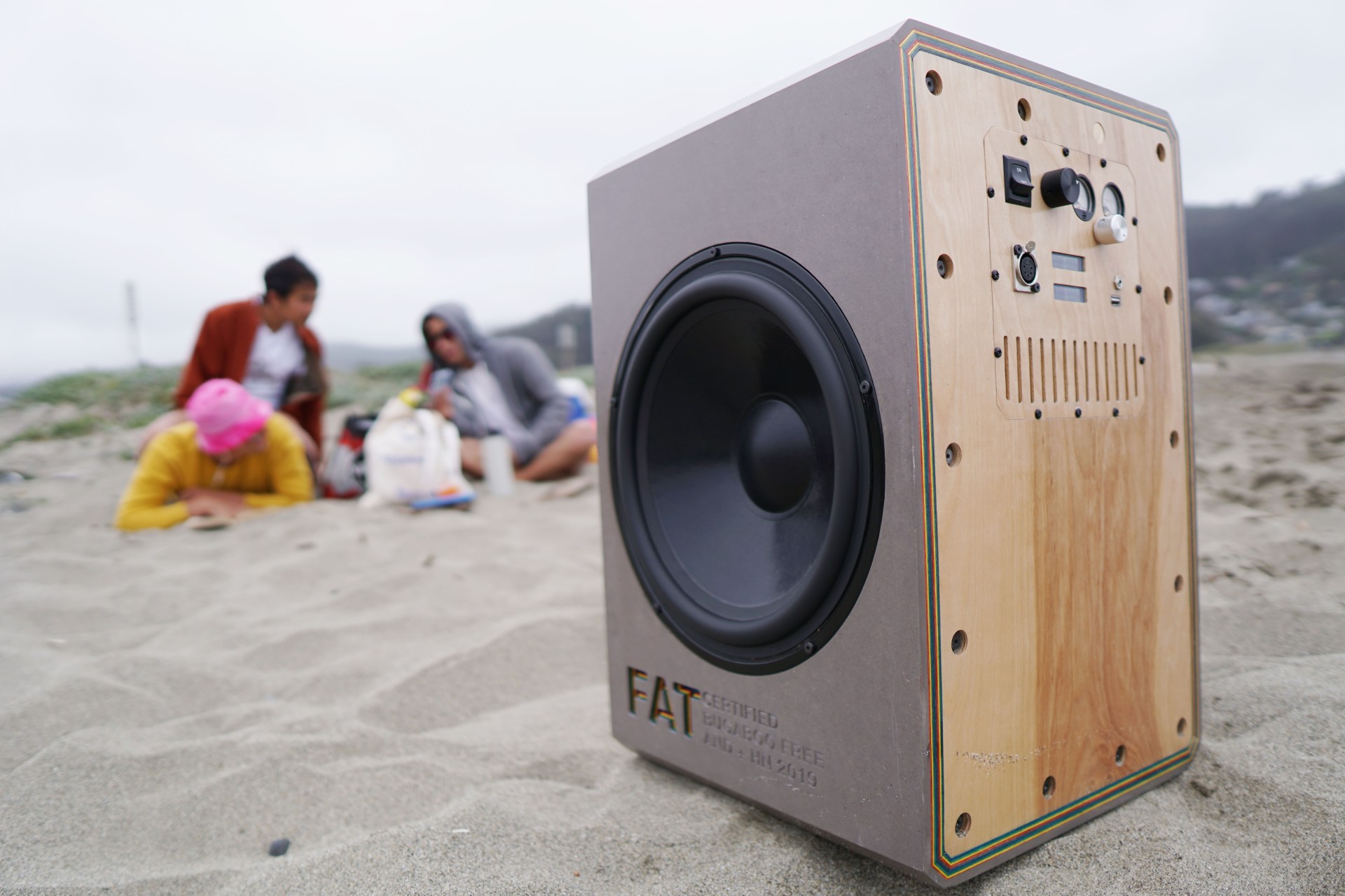
Back by popular demand. Here’s how I designed the electronics to power the 120 dBSPL (@ 1m, ±3dB 40Hz-20kHz) beast to defeat the new generation of super mid “Soundboks” type devices.

As you can tell there are some peculiarities to this design, including a dual battery rails supporting the “low power” section.

POWER

THE AMP
The first thing to do is to down-select the amplifier chip-set to deliver the hundreds of watts required to hit target levels.

There are very few amplifiers in this power range that will meet this need.

  • IRS 2092 with ±50V rails and adequate MOSFETs
    • ruled out for the reason that I don’t want to source ±50V
  • WONDOM AA-AB31395: 1 X 1000Watt Class D Audio Amplifier Board – T-AMP – LV
    • Out because 500W into 4 Ohms @ 10% THD @ 60V
    • No THD/Power curves
  • WONDOM AA-AB35511 3 X 500Watt Class D Audio Amplifier Board – T-AMP
    • Out because it actually can only sink 300W into 3 ohms @ 50V @ 10% THD
  • ICEpower 300A1: single channel 300W @ 1% THD @ 55V
    • this is a strong contender, but it’s single channel and requires a ±12V input and is therefore slightly more expensive and complicated than the TPA3255
  • ICE Power 500ASP
    • Honestly more than perfect but requires 120V AC
  • ICEpower 300A2
    • Also an incredible amp but requires ±35-65V which is annoying with batteries
  • TPA3255 Capable of 500W into 4 ohms (PBTL) @ 50V @ 1% THD
    • best contender
    • 3e-audio sells a balanced input version which is great for low noise!

The TPA3255 chip-set is the winner here for cost and simplicity while maintaining high quality.

In my experience, a lot of these amps will “overspec” their power output, as they’ll rate their amp in a very specific set of conditions. Let’s dive further into the TPA3255 to confirm it can meet our needs. There are a few dimensions we care about:

  • power required by speaker to hit target SPL
  • impedance of speaker at frequencies of highest power
  • voltage/current required by amplifier at highest power

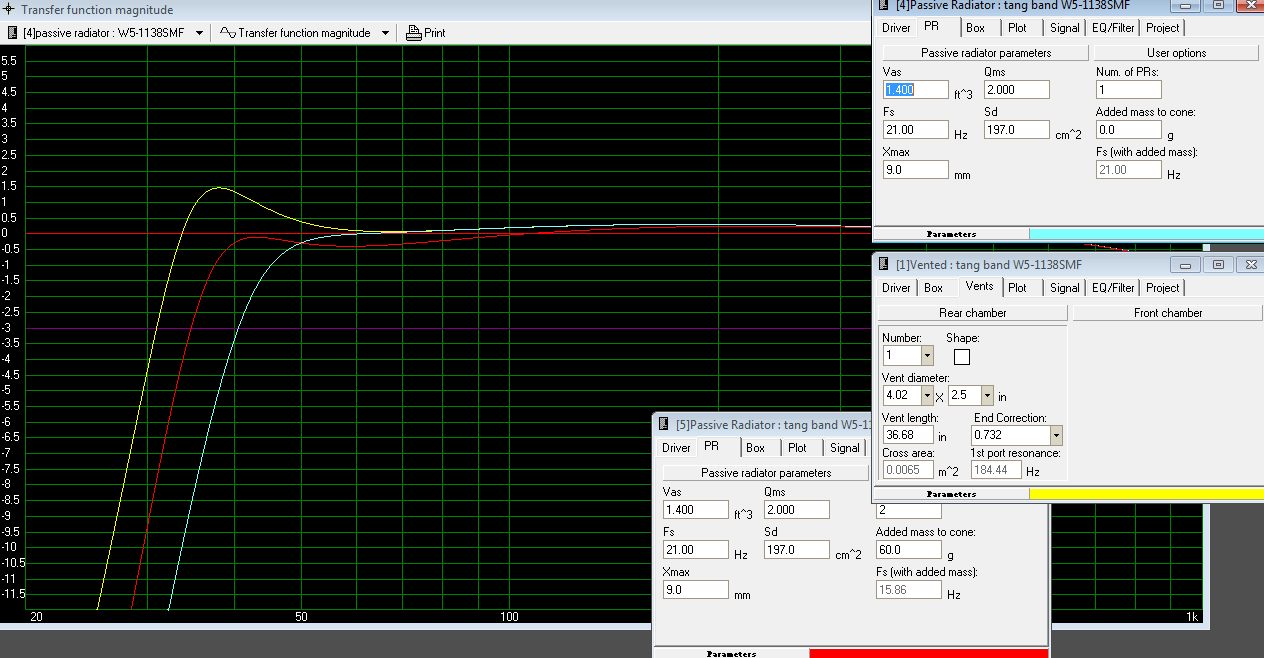
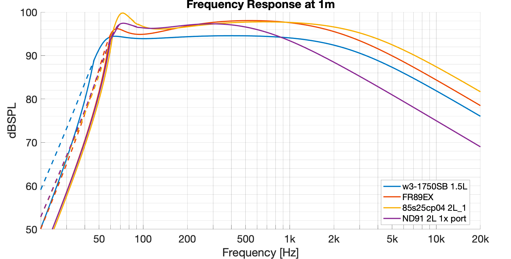
Woofers are almost always the least efficient and most power intensive part of an acoustic system, so we’ll focus on the woofers for now. To determine “how much power into what impedance” we refer to the target response from the simulation in part 1 and check power required and impedance:

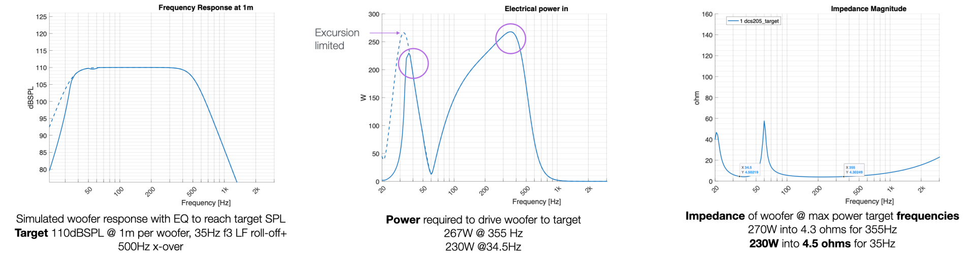
So we need 270W into 4.3 ohms at 355Hz and 230W into 4.5 ohms at 35 Hz! Then we refer to the TPA3255 data sheet to determine if it can deliver that power:

Based in the data sheet, it looks like we can do 260W into 4 ohms, which is precisely 231W into 4.5 ohms—perfect!. The amp will not be able to deliver the full power required at 355Hz, but that’s OK—that’s firmly in the lower vocal range, where I expect less general signal level in normal use. The data sheet also informs us that the amplifier expects 54V to deliver this wattage. We can then refer to the efficiency curves to understand the maximum current the amplifier will draw:

Based on these two graphs we can expect that for two woofer channels we’ll be looking at a maximum power draw of about 700W. We can apply this same process to the mid-range and tweeter to determine the total power draw of all 4 channels of this speaker, but to cut to the chase, we’re looking at a power draw of about 1kW peak.

From Ohms law, we can determine that 1000W at 54V is about 18 Amps, which we’ll use to spec the power supply portion. For now, we can be confident that the TPA3255 amplifier will suit our needs.

3e-audio’s TPA3255 boards are also beautiful, compact and expensive. Here they are in the (as typical for every project I do) completely undersized electronics box.

THE BATTERY
Based on the acoustic simulations above, the power draw for the whole system looks something like this:

The peak load of about 1kW is an absolute maximum— all of the driver’s stated power handling exceeds their actual linear excursion (in simulation). We need to be able to deliver 1kW for transients but an actual input (sine wave being the worse case equating to 1kW peak) would destroy the speakers rather quickly. I accidentally verified this fact when I mis-programmed the DSP, which caused it to output full-scale white noise; the tweeter burnt immediately. Armed with this knowledge, I can happily specify a 48V 1kW battery to handle the peak demands. The continuous load—i.e. the crest factor (or the ratio between the RMS value and peak value of a signal)—for very loud music content will be <-10dB below this peak, so the battery will be chillin’. Not only is -10dB the 99th percentile of music loudness (more on this later), but most playback environments (e.g. Spotify) have a metadata normalization scheme that limits CF to < -14dB.

Moving on to runtime, my target was “a while” at max volume, 6 hours for party usage and ~all day for normal-to-loud listening levels. I added a quick calc in the bottom of the power table—a typical battery capacity in the 48V range is 20Ah, which yields about 2.75 hours at maximum power output with music, and 5.63 hours at a click or two down from that (-6dB). Keep in mind, this is still using -10dB CF, which is, like, hella loud. For reference, the crest factor of a loud metal song like System of a Down’s “Take the Power Back” is -14.2dB. Taking that into account, 20Ah seems like a reasonable capacity.

Writing this from the perspective of having already built the device and used it for parties, the battery life is great. Max volume is enough to irritate the house next door and more than enough to cover a 30 person party on the beach, the battery typically lasts for about 6 hours in this usage, so -10dB CF is certainly a very aggressive estimator for battery life.

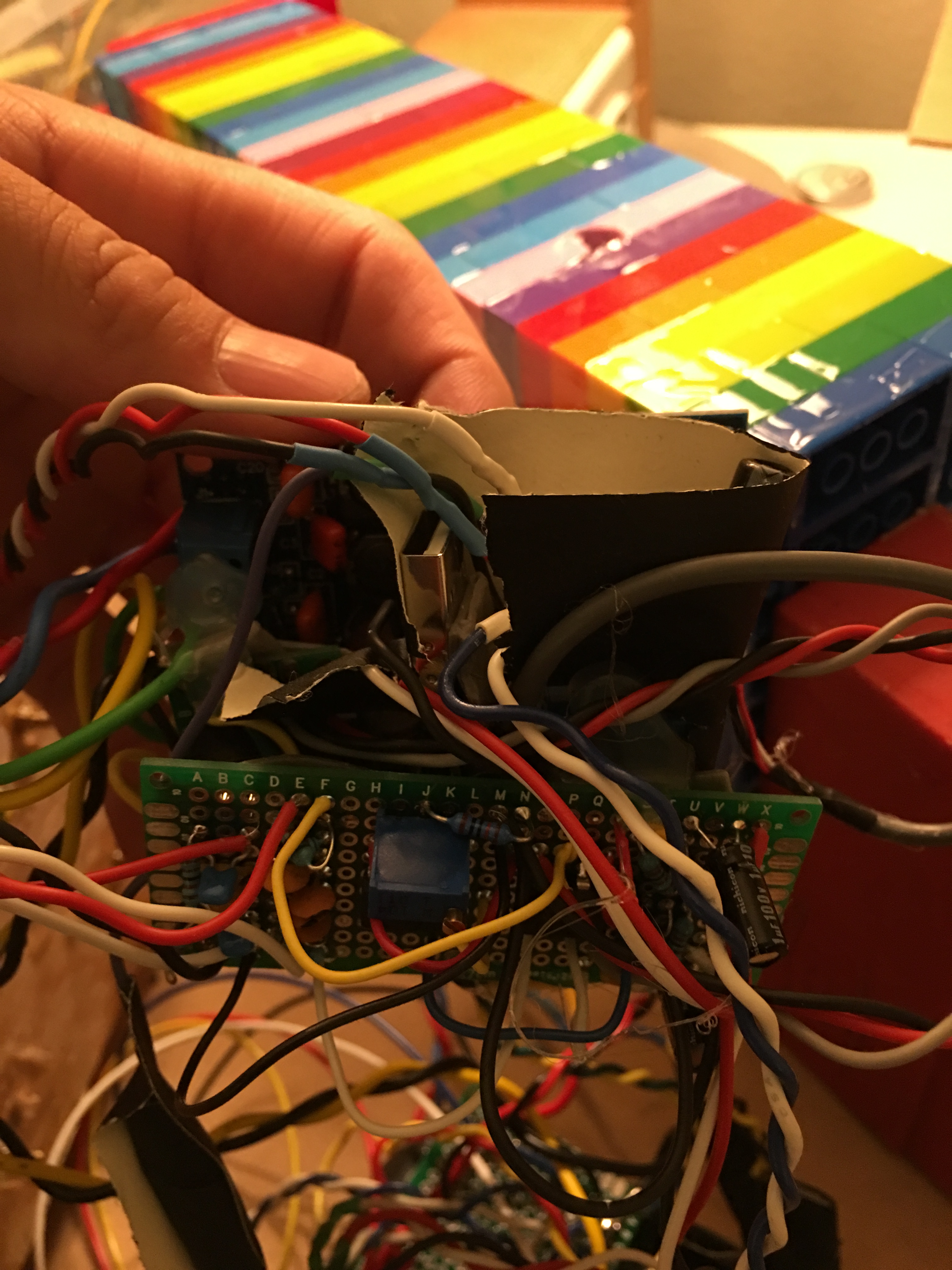
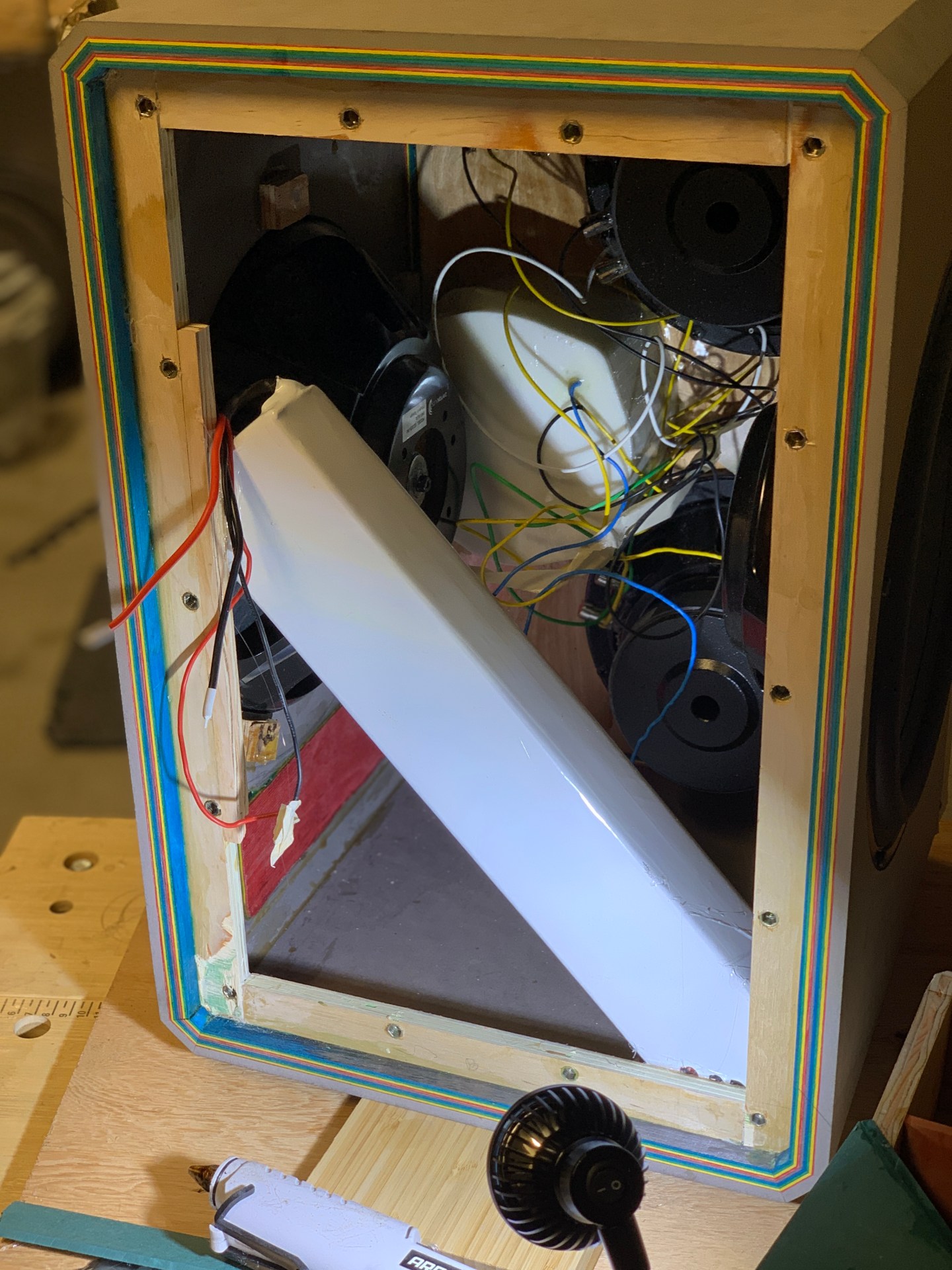
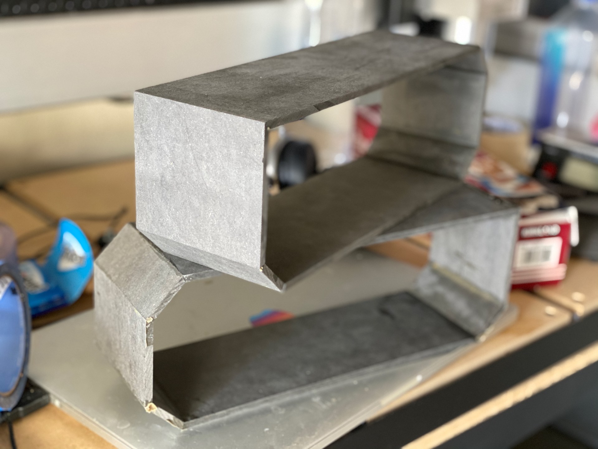
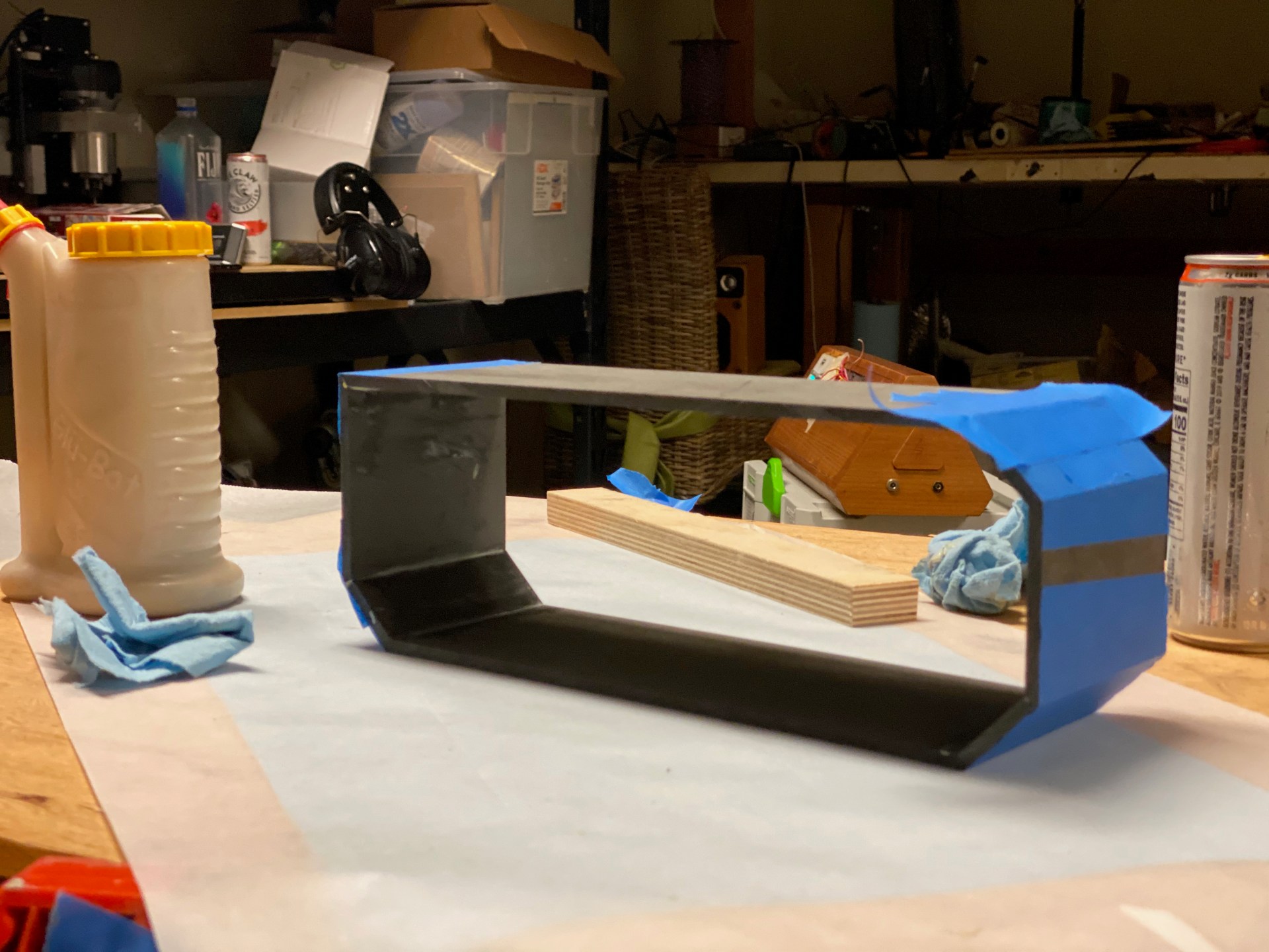
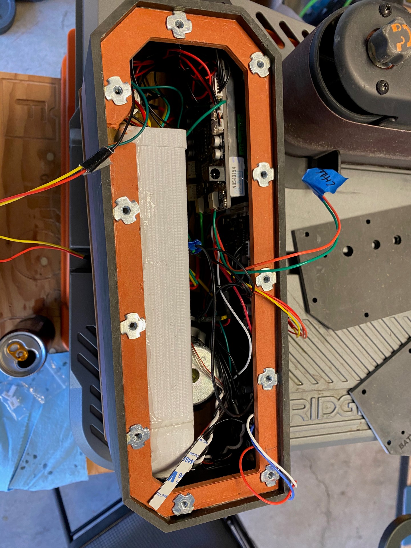
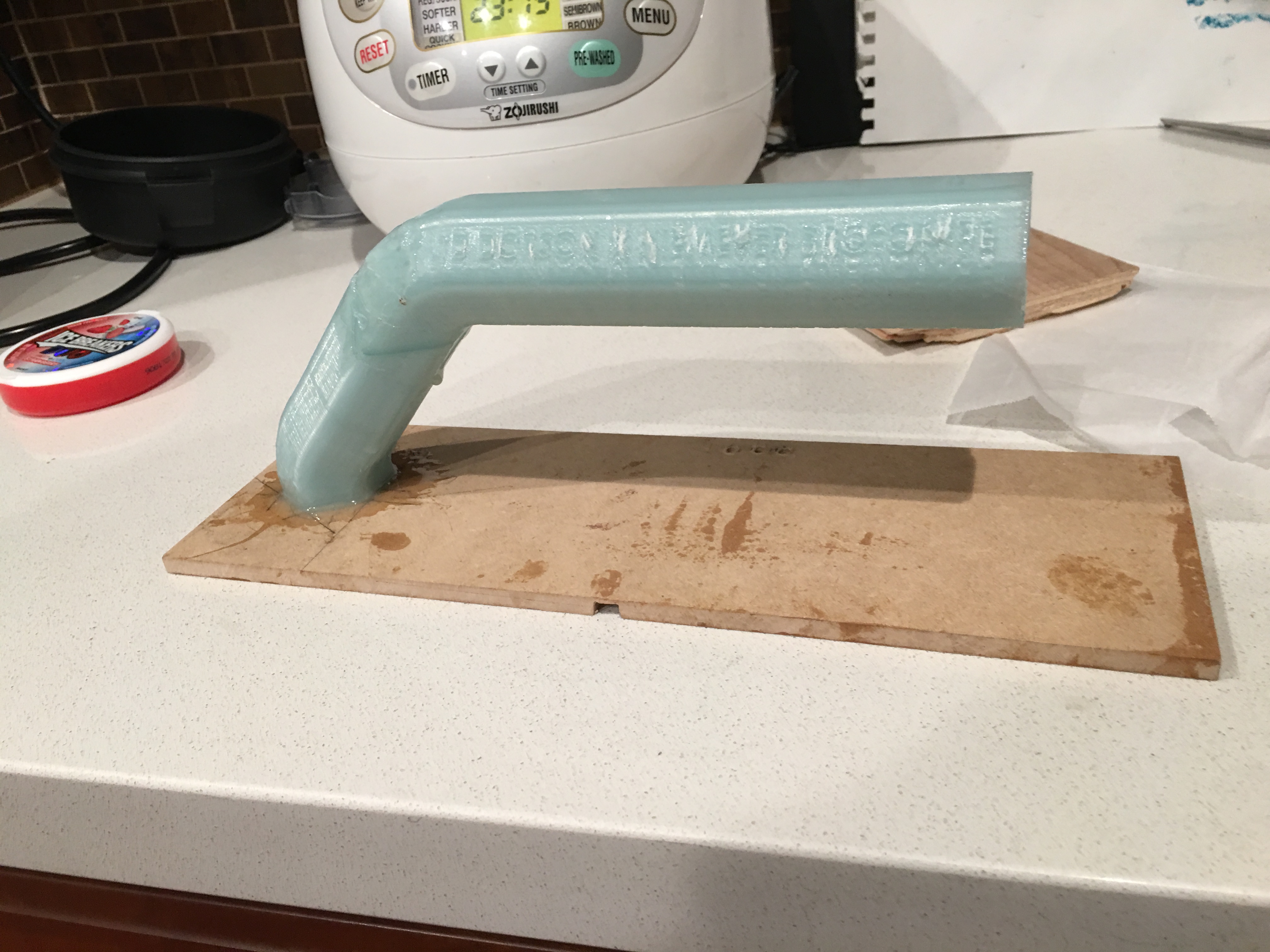
One thing not mentioned so far: a 20Ah 48v battery is massive. I had trouble fitting it into box in any orientation that did not interfere with the isolated electronics box, so I had to glue it in at an angle and take a chunk out of the electronics box:

big white rectangle is battery
electronics box from above with a nice miter through it

DSP AND TUNING

SIGNAL CHAIN

The beauty of the TPA3255 by 3eAudio is that it runs a differential input which is massive for noise management. At the time, 3eAudio also sold a beautiful differential-out DSP board with an integrated Bluetooth chip. The integration of the BT chip eliminates BT radio noise at the source while the differential signal chain allows the removal of any injected EMI or ripple noise on the voltage sources.

from 3e-audio’s website

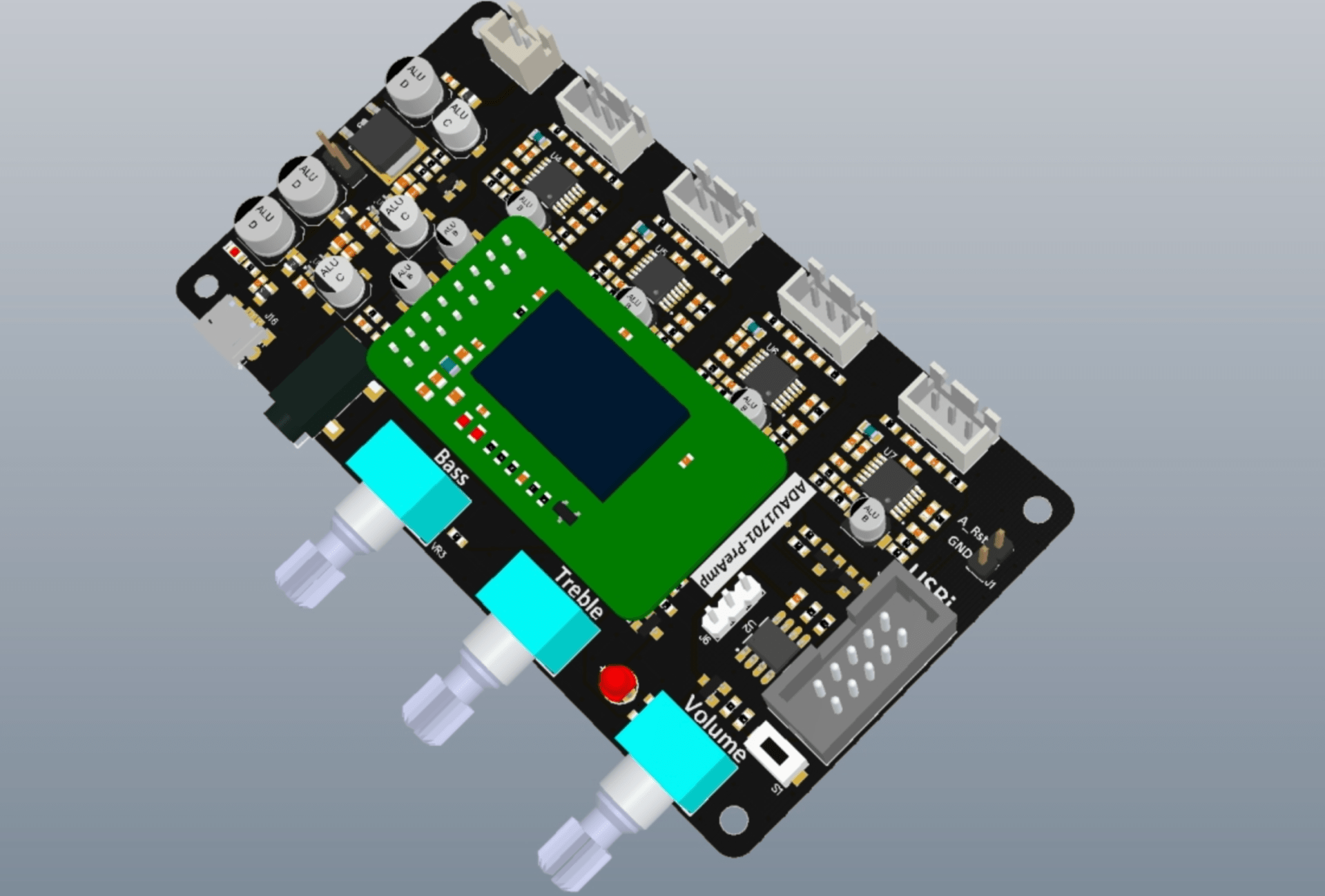
This nearly fully integrated solution simplifies a lot of the process for creating a low noise signal chain. The amps themselves have a 12V line to run the DSP off of! However, I ended up forgoing this 12V rail for something much more ridiculous (see noise section)

Tuning with ADAU1701 is a breeze once you figure out SigmaDSP’s interface and how to write to EEPROM (hint: you have to right click).

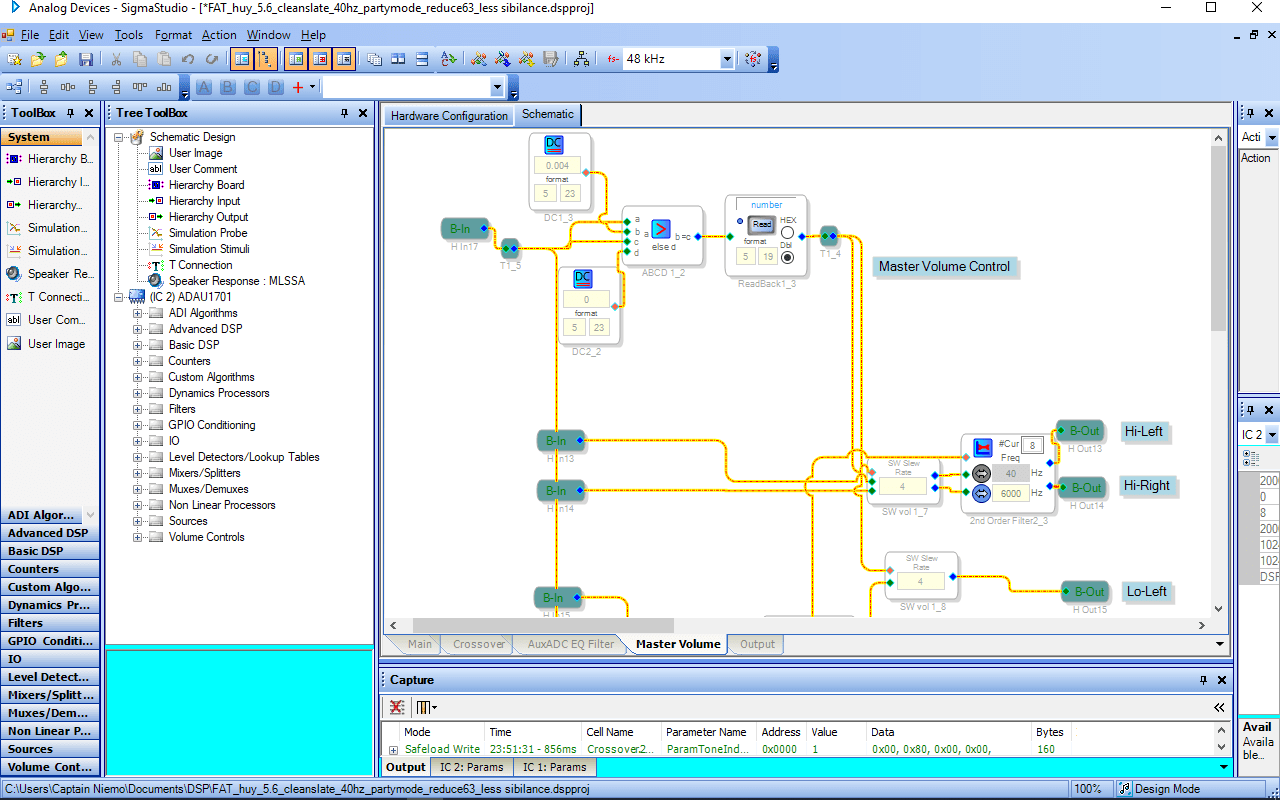
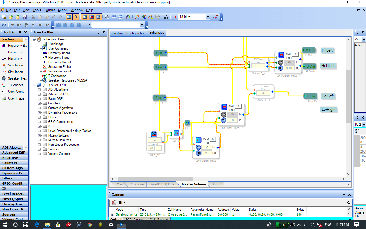
Here’s an overview of the DSP employed to get this beast of an acoustic system sounding good at all levels:

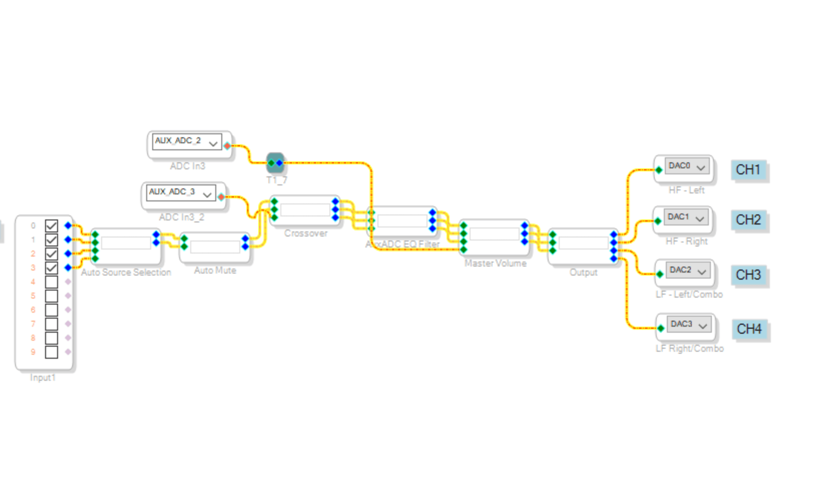
The first block labeledx-over handles several global EQs as well as some volume-tone compensation. Here’s the signal flow:

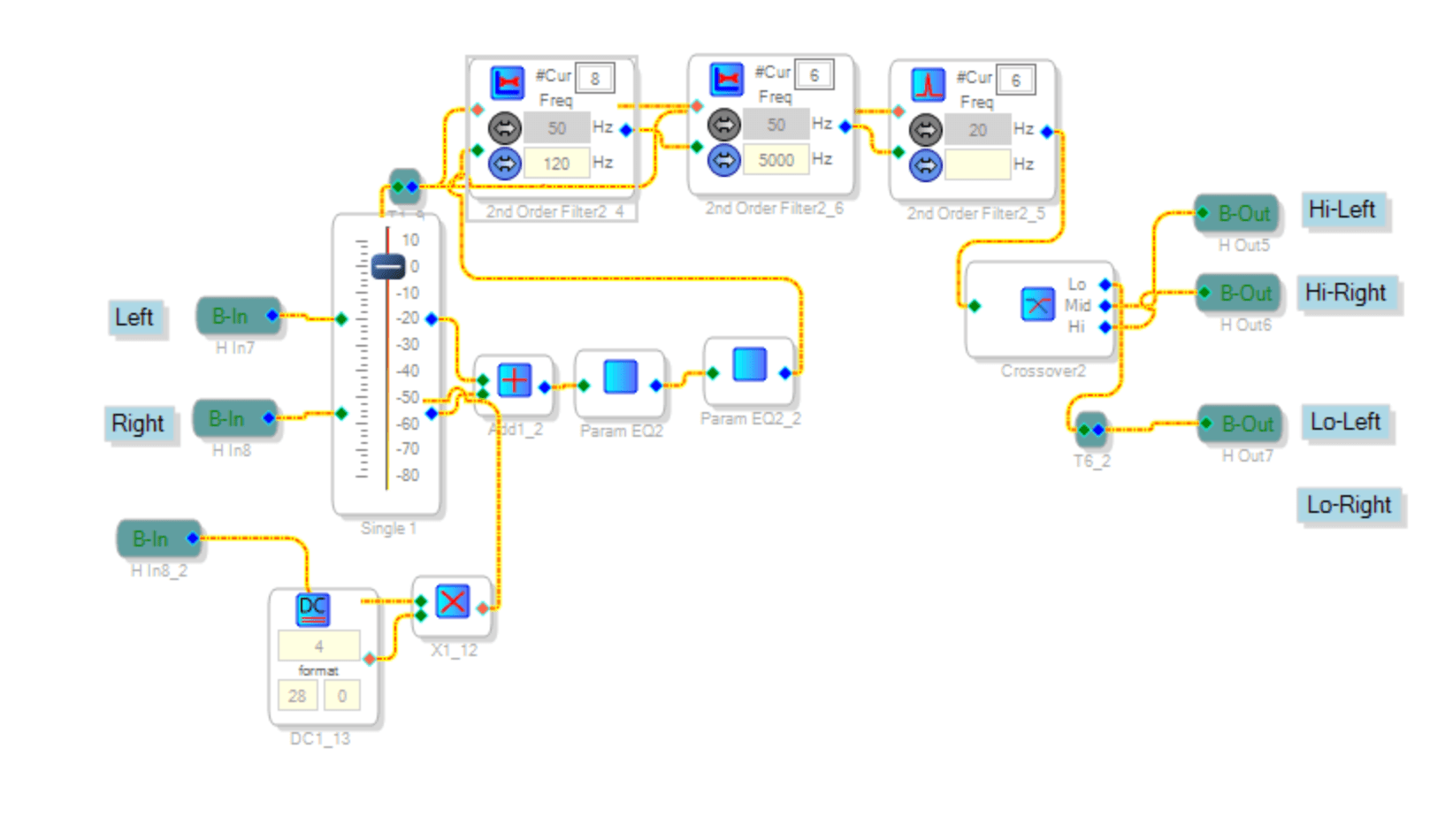
Inside the first parametric EQ, the analytical for the midrange and tweeter takes out the resonance peaks (occurring from horn loading, and the rear-mounted design of the mid-range).

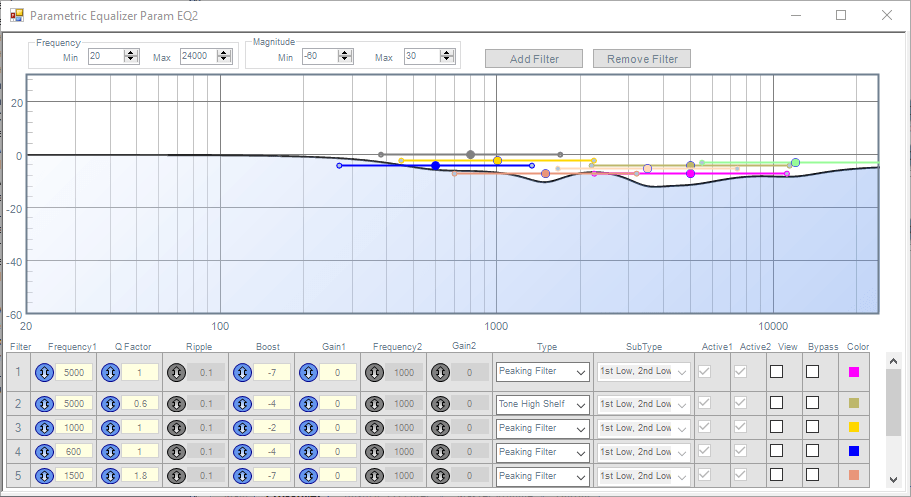
Inside the second EQ block is an absolute mess of peaking filters to carefully control the excursion and system resonances of the woofers and the woofer box.

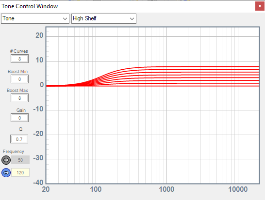
After the parametric EQs are a bunch of volume control filters which have a very specific and unusual function: to enable party mode. The intent of the party mode knob is to shape the output of the whole system to be focused on higher output. Ideally, the whole system has been tuned for a very pleasant Hi-Fi response, with rich, deep bass, balanced vocals, and sizzling highs. But sometimes you just want a little extra punch, and that’s what party mode is for.

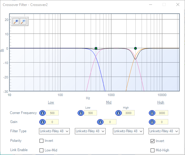
X-over, as low as possible for the midrange and tweeter to limit directivity effects. Two notes:

  1. Typically crossovers are a bit higher for this kind of application (800-900Hz), I am of the personal preference to push crossovers as low as possible for better efficiency and directivity. Generally I think the worry for low crossover is either distortion due to high excursion at resonance, but with careful calculation and proper DSP, this can be easily avoided.
  2. The LR alignments often prefer a phase inversion for the TW for proper summation, which can be confirmed in real life by measuring in the farfield.

Moving on the the next section: the master volume!

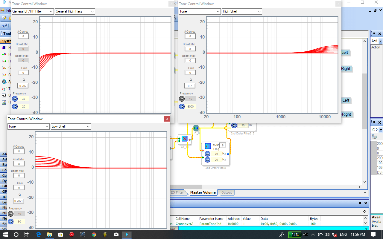
These essentially are optimized to allow maximum excursion at a variety of levels, while also respecting the equal-loudness contours (in short, our perception of a “flat” frequency response changes with a change in output level; lower listening levels require more bass/treble to sound balanced). The HP filter moves down as volume moves down, while the low shelf increases LF gain, allowing deep bass at lower listening levels and controlling over excursion at high levels. A similar behavior is required for high frequency.

Finally, the output stage requires some gain reduction for the more sensitive mid-range/tweeter, an overall lowpass for the subwoofers, and a soft clipper to limit digital distortion:

THERMALS, NOISE AND ACCESORIES

THERMALS

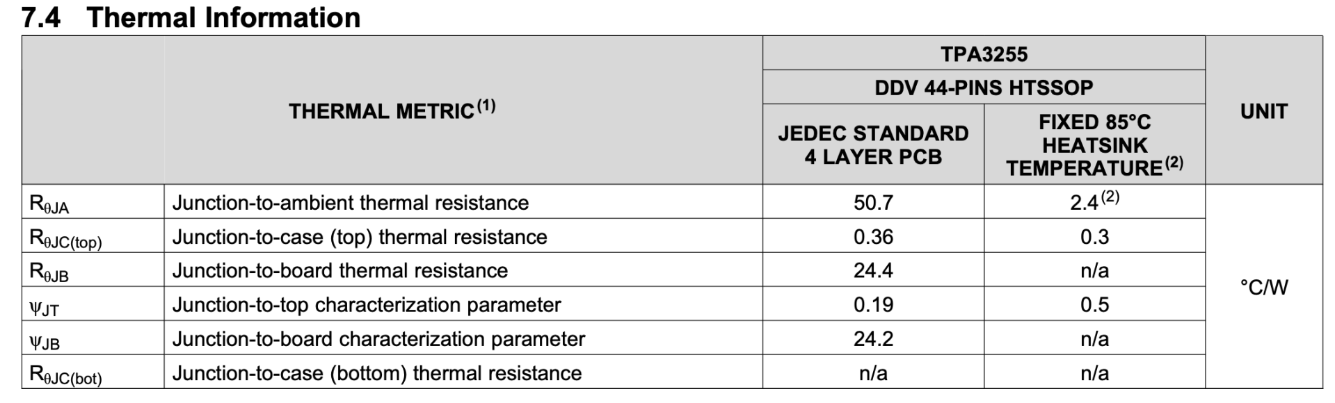
While in theory the idle losses of the TPA3255 (2.5W) should only imply a 6°C rise with Junction-to-ambient thermal resistance of a fixed 85°C heatsink, it turns out that 1) thermals are much more complicated than that and dependent on a multitude of design factors 2) in reality the TPA3255 with a heatsink gets quite hot at idle.

Further still, the power dissipated by the amplifier rises non-linearly with output power, and at the (woofer) rated 600W total output power, the amplifier will be dissipating nearly 90W in heat. While 600W is the upper boundary (consider duty cycle, crest factor, etc), again, in practice, what I observed is that the amplifier gets hot hot. For instance, standard wire (PVC) temperature ratings are ~80°C which only allows a maximum output power of 100W total (assuming ambient at 25°C and an ideal heatsink).

To combat this, I installed thermo-couple controlled 80mm case fans to the heatsinks, with exhaust vents in the electronics box, to enhance the heat dissipation capacity of the system and prevent heat-soak. I also upgraded some the wiring for this project to silicone-sleeved wires, which besides tasting great being luxurious in quality and feel are much easier to route, handle and bundle.

in this terrible picture you can see the Arctic F8 TC case fan nestled right above the heatsink

ACCESSORIES AND NOISE

The fans themselves consume enough wattage that the TPA3255 onboard 12V line was not sufficient. I also wanted a battery meter, and a backlight VU meter. I trialed a HV DC-DC step down to run all the 12V auxiliary bits; in most applications, I would use a simple low noise buck converter like an LM2596, but these tap out around 36V. To step down the 50V battery voltage, I had to find specialty voltage converters, but the ones I found for reasonable prices tended to inject too much noise into the signal path. Due to the high gain and high efficiency of the acoustic section, the whole set up caused tons of quiescent noise, which only increased with the power draw of the aux electronics (e.g. fans). So I opted for a truly ridiculous solution.

‘DC-DC converters do come in various flavors of ground-loop isolation, ranging from 0 isolation (cheap) to kV of isolation (very expensive for higher ampacity), but you know what’s cheap and intrinsically highly isolated? A completely floating power supply.

Having lost all sense in the pursuit of FAT bass, I built a separate 3S battery pack to run all auxiliaries which has the advantage of excellent isolation and the massive disadvantage of added complexity. In addition to having to have two battery management boards, two separate grounds, carefully calculated battery capacities, the device now requires two separate chargers and a 4-pin charging connector.

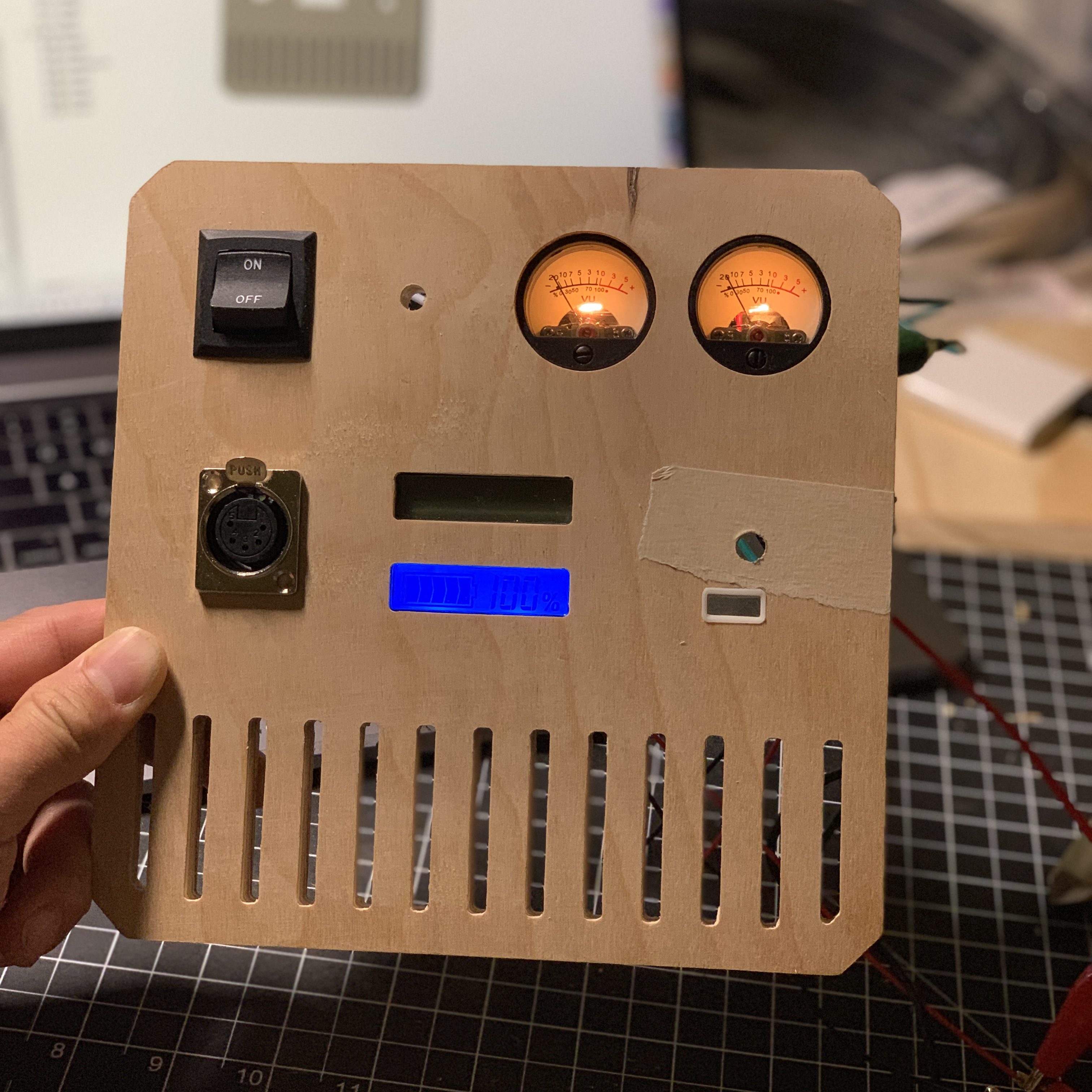
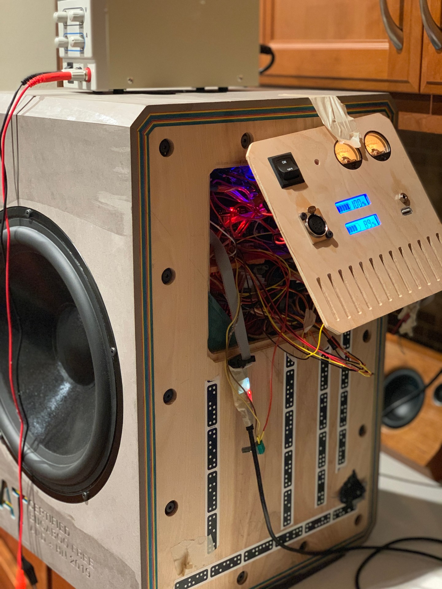
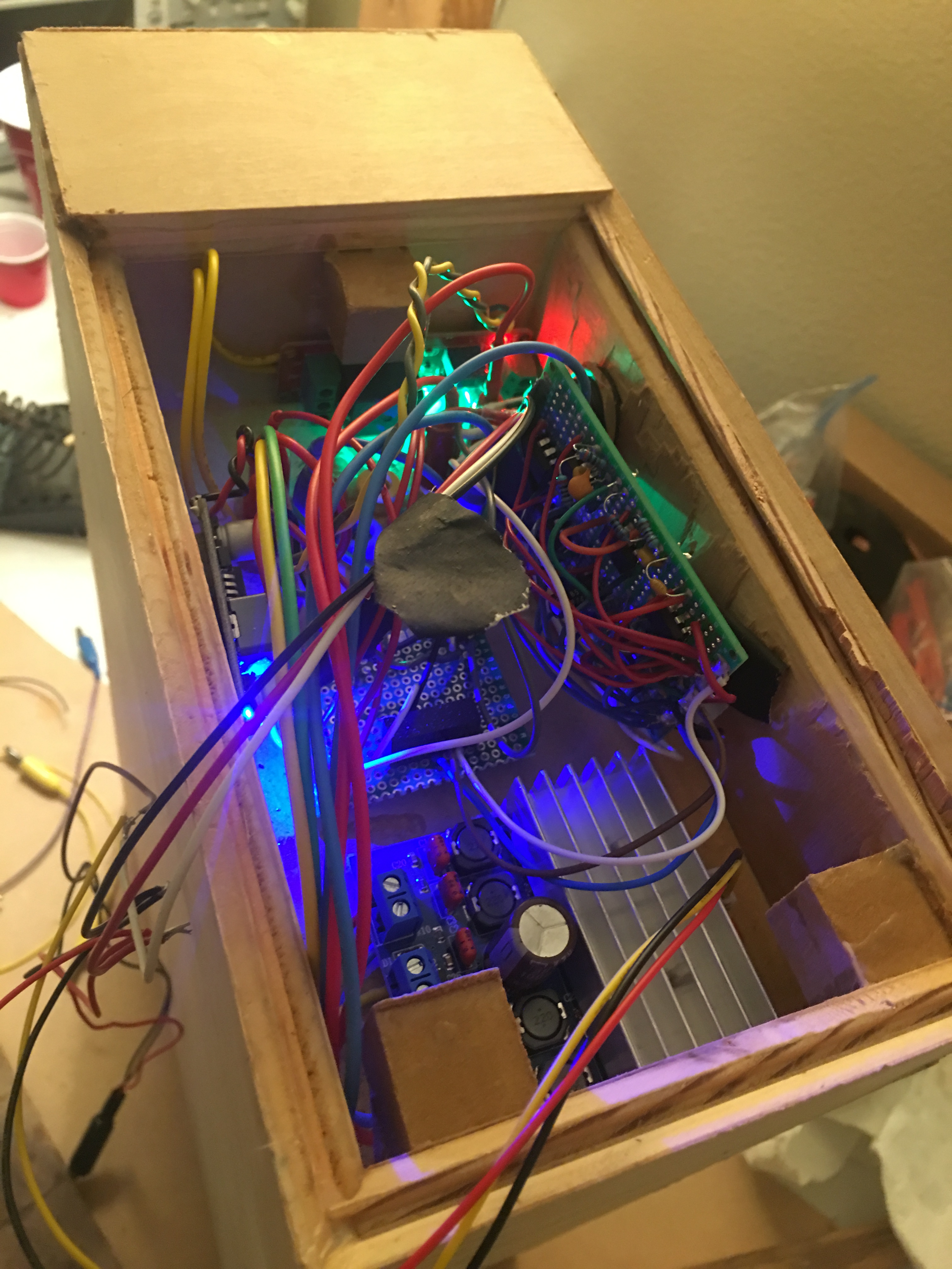
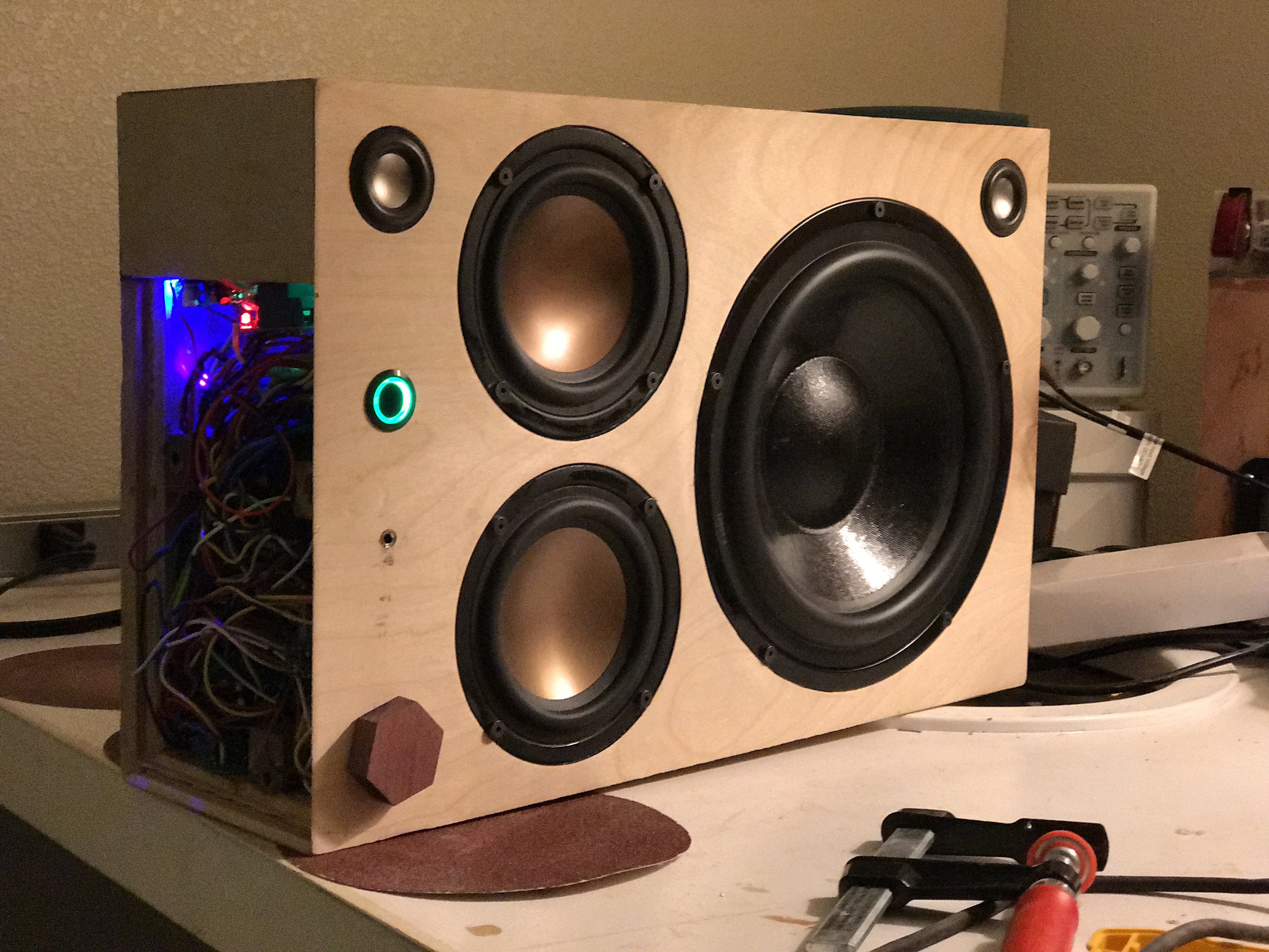
But it was all worth it for the VU meters, which flick to the beat independently:

FINISHING THE BUILD

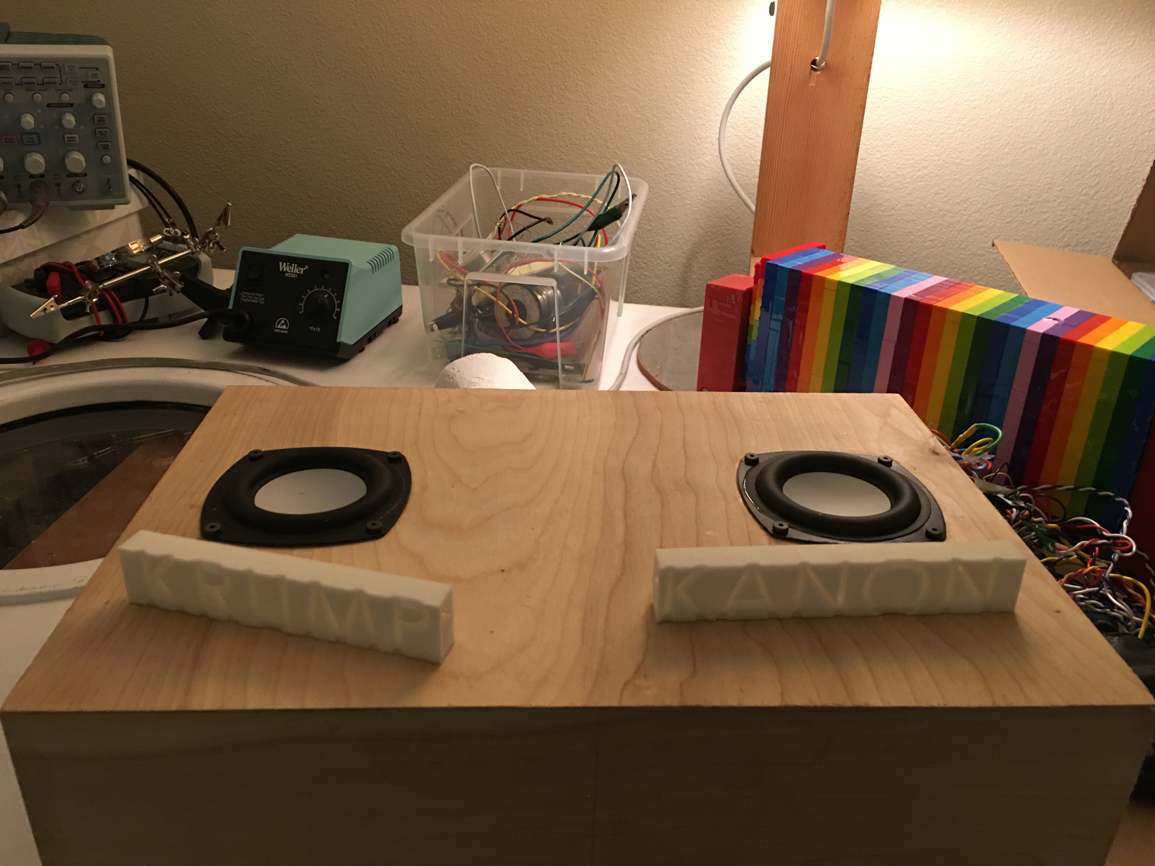
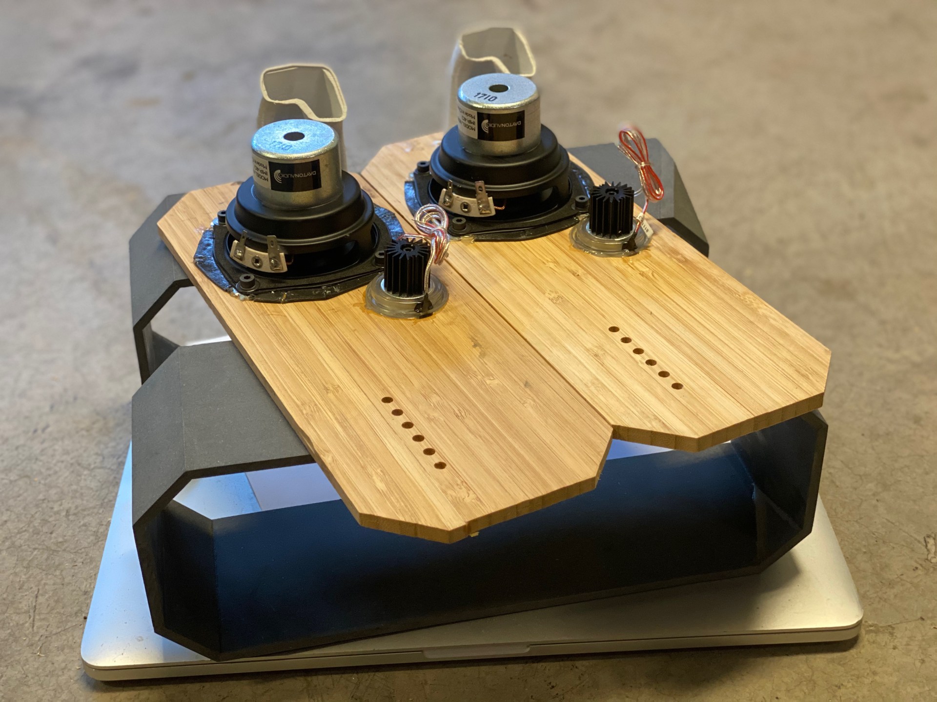
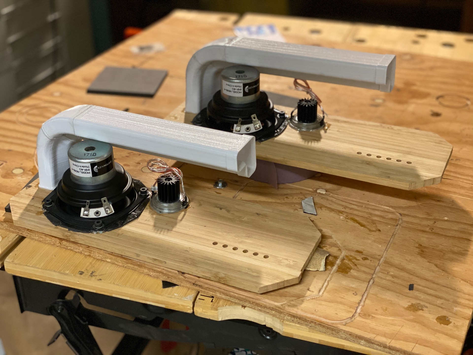
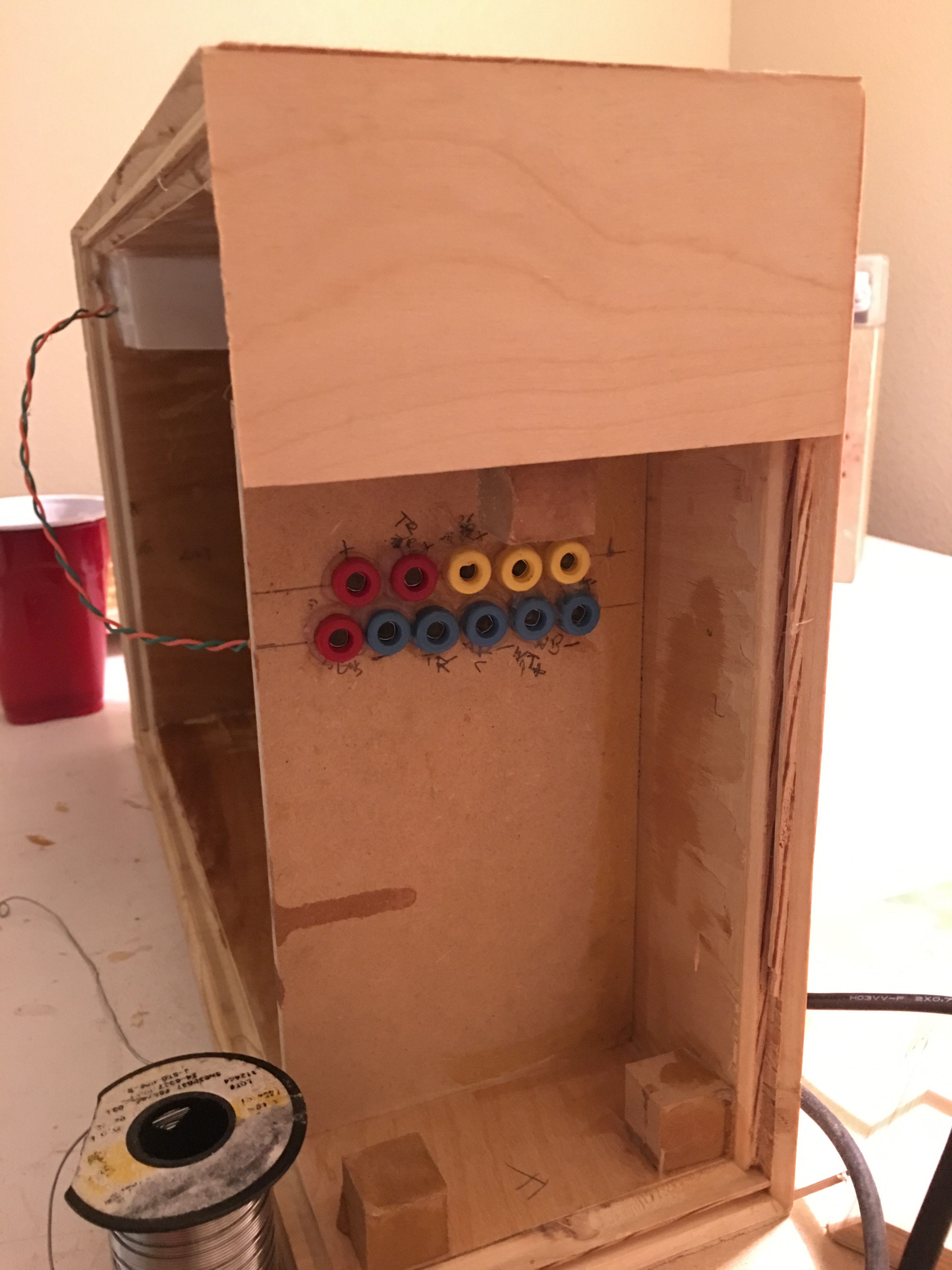
At this point, all that was left was to put everything together

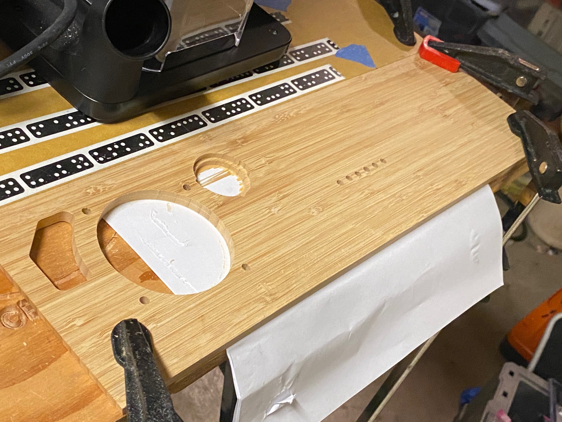
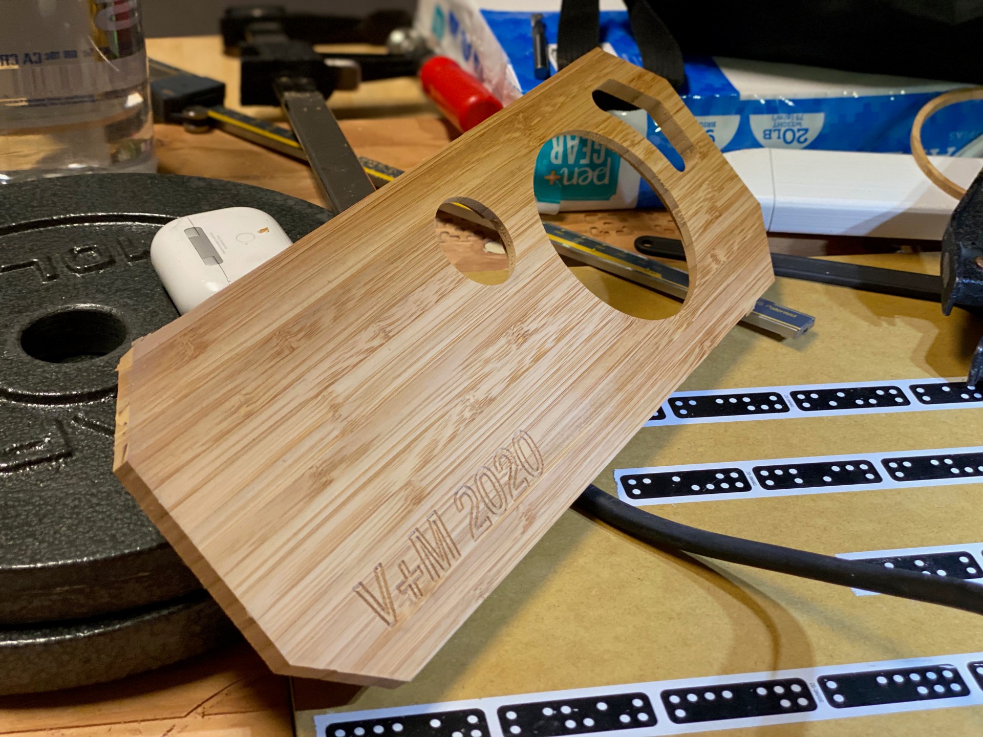
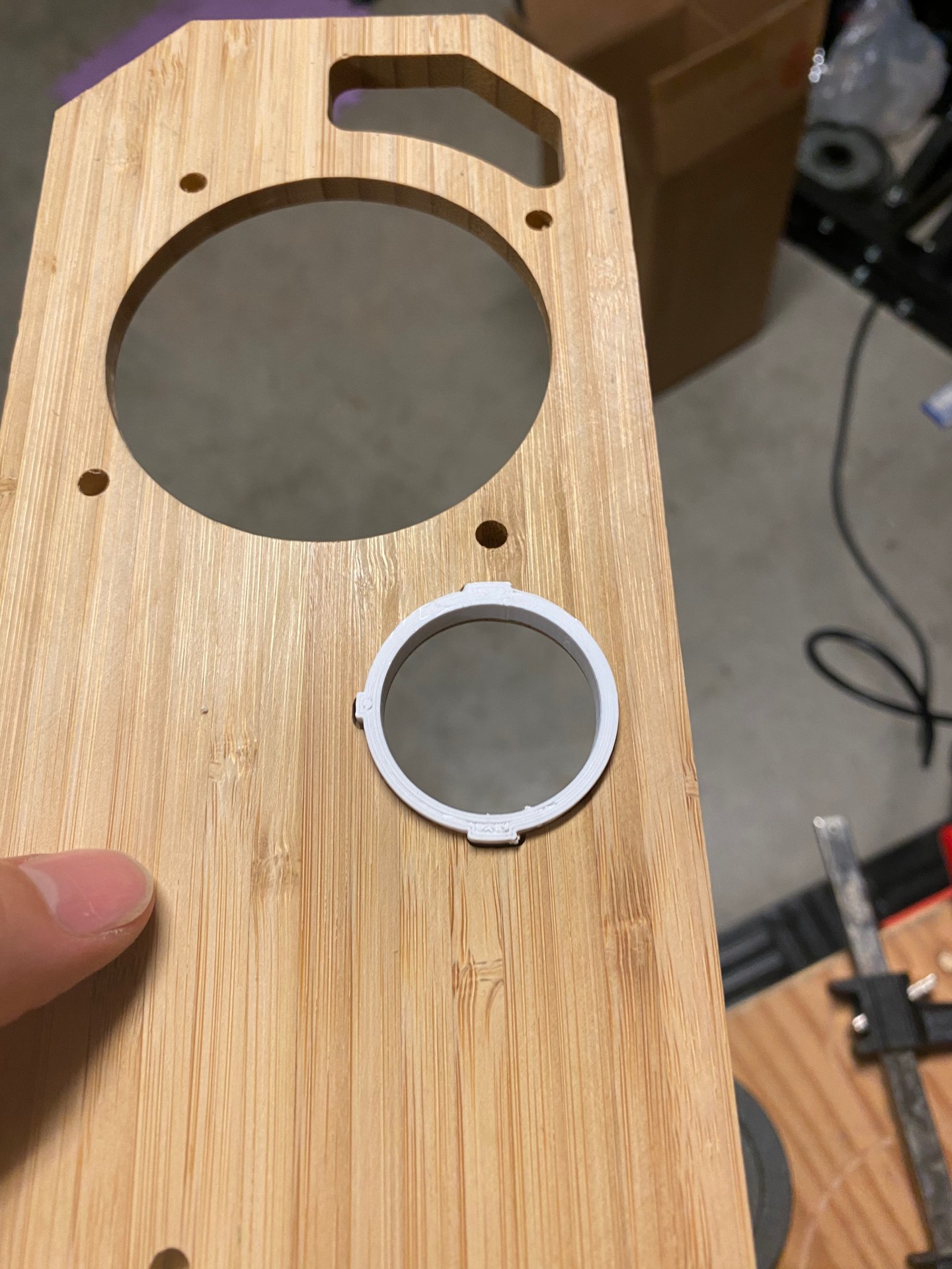
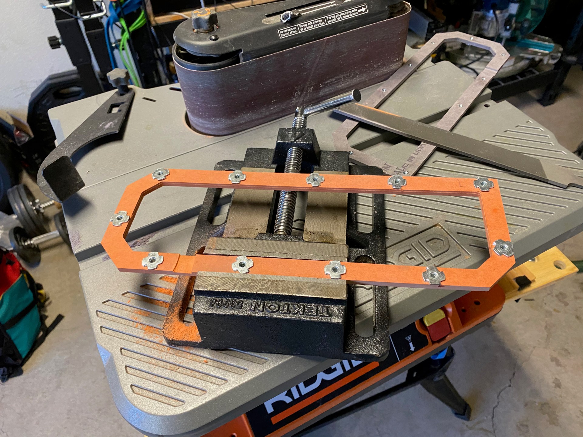
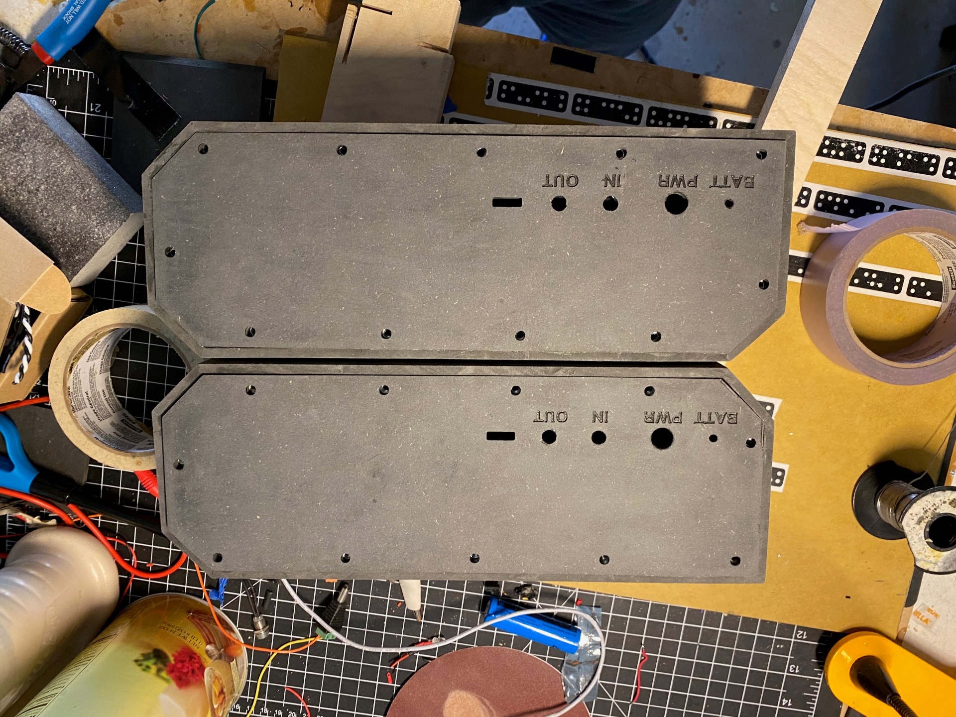
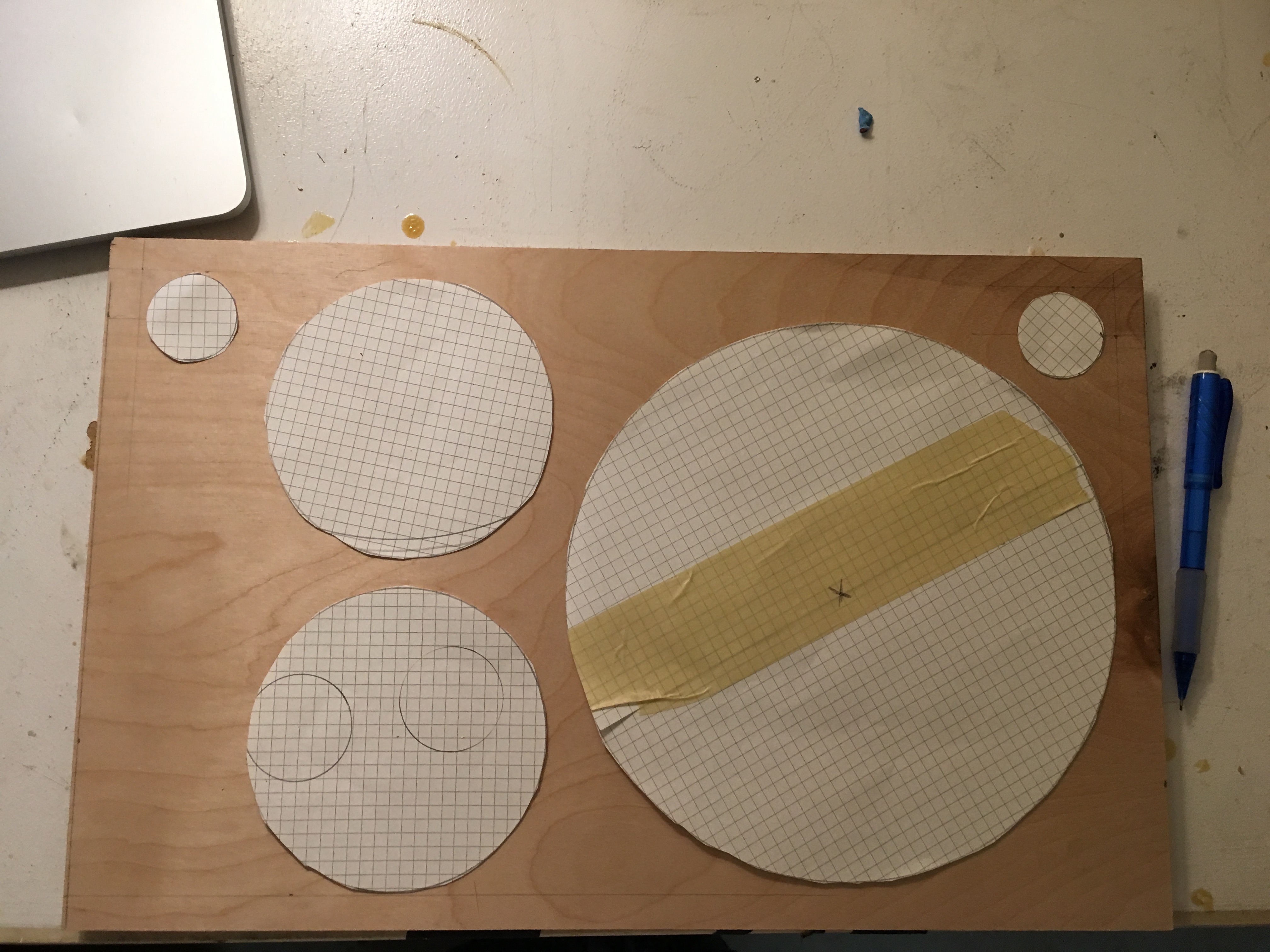
Testing the cut outs for the rear electronics panel:

The VU meters look amazing:

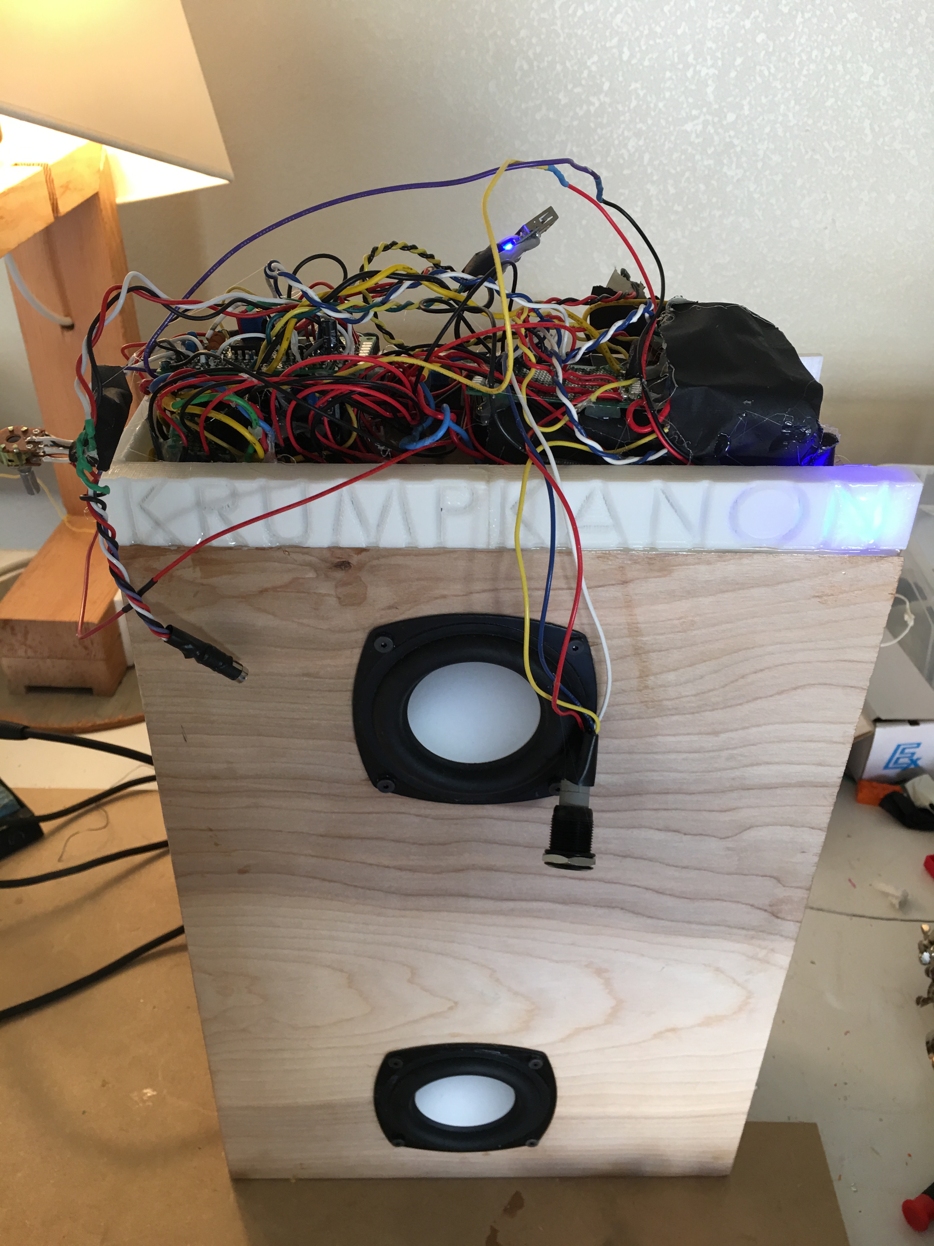
Adding stuffing, and a mess of wiring

The wiring can only get more messy

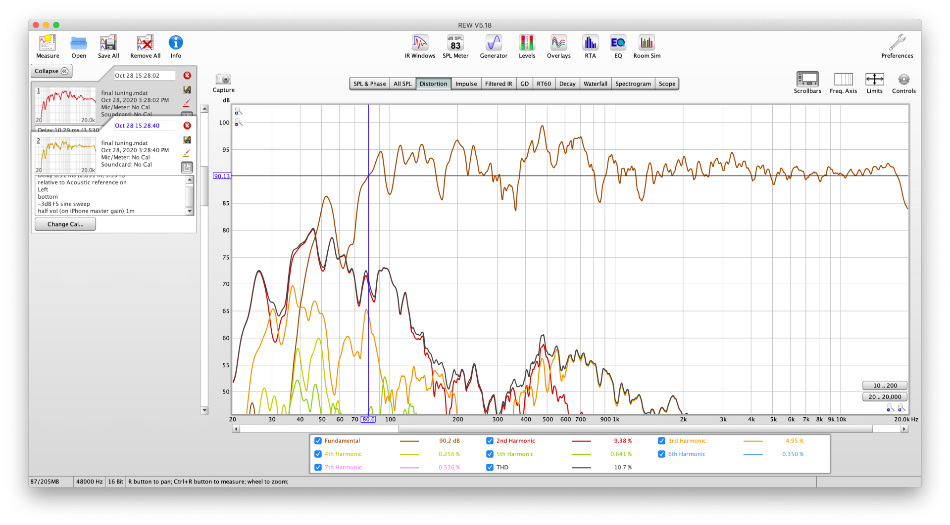
Sound testing before finally assembly:
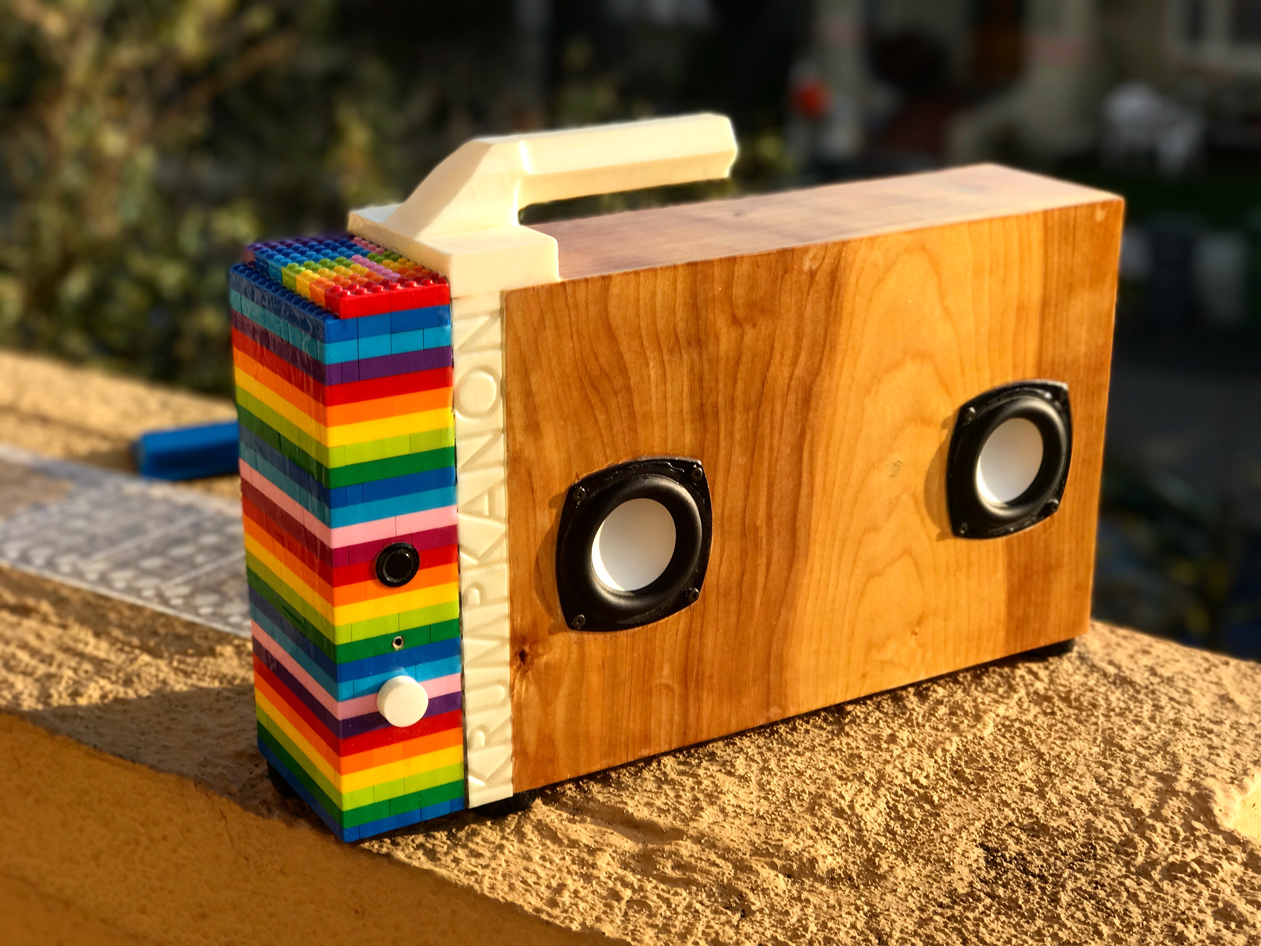
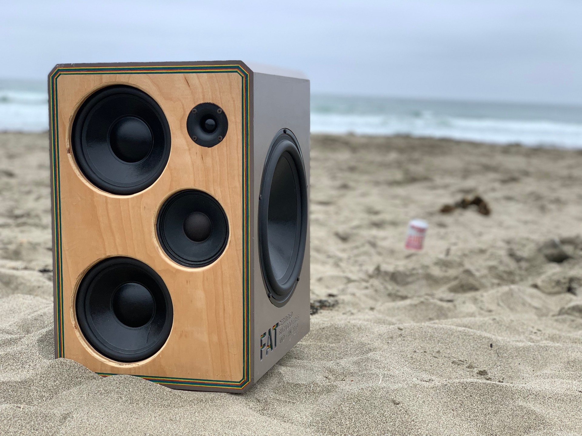
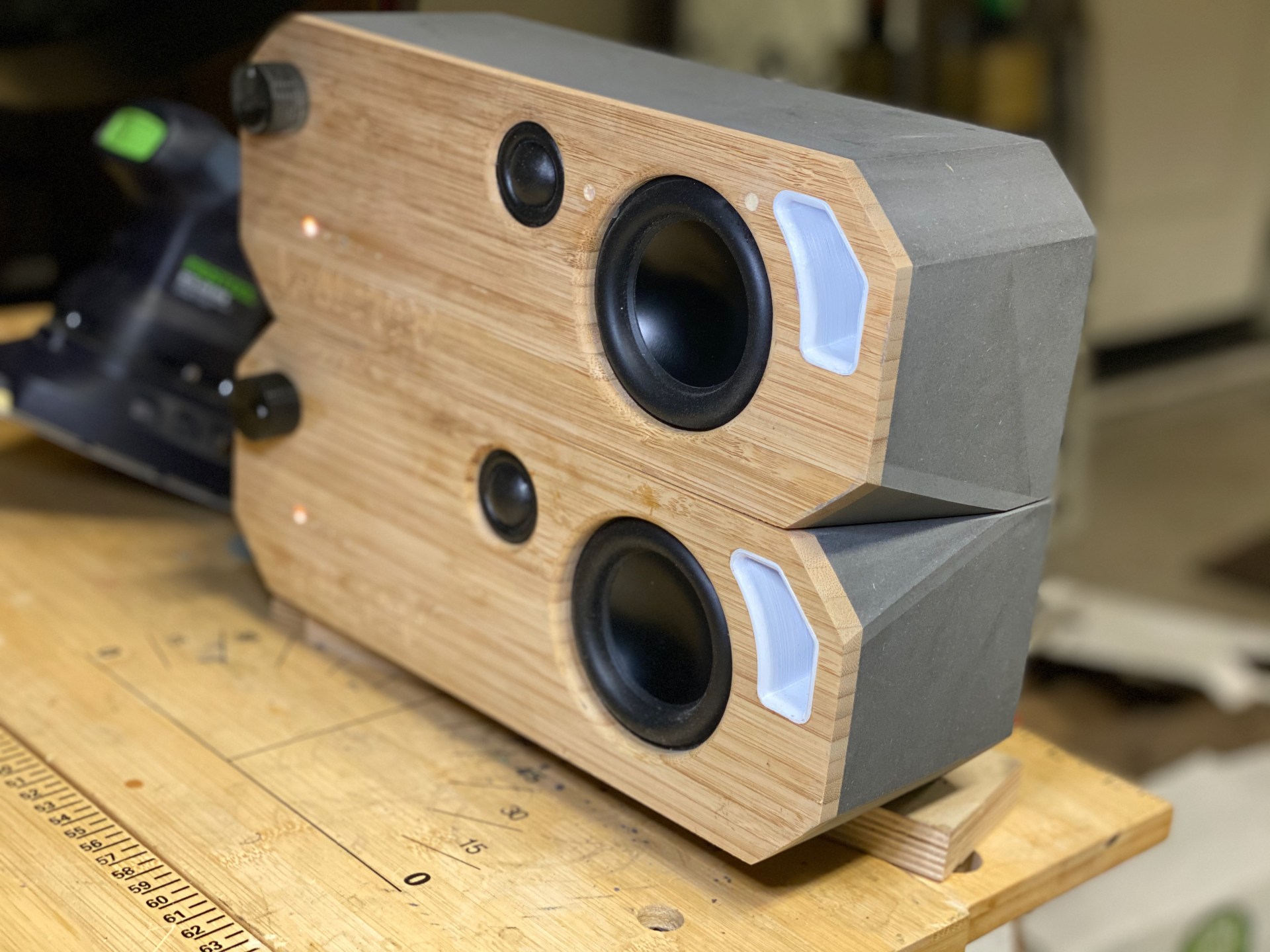
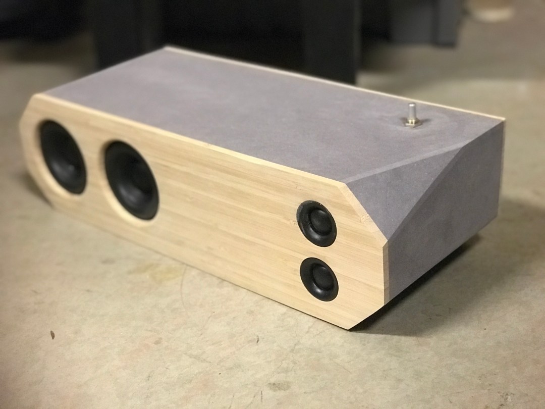
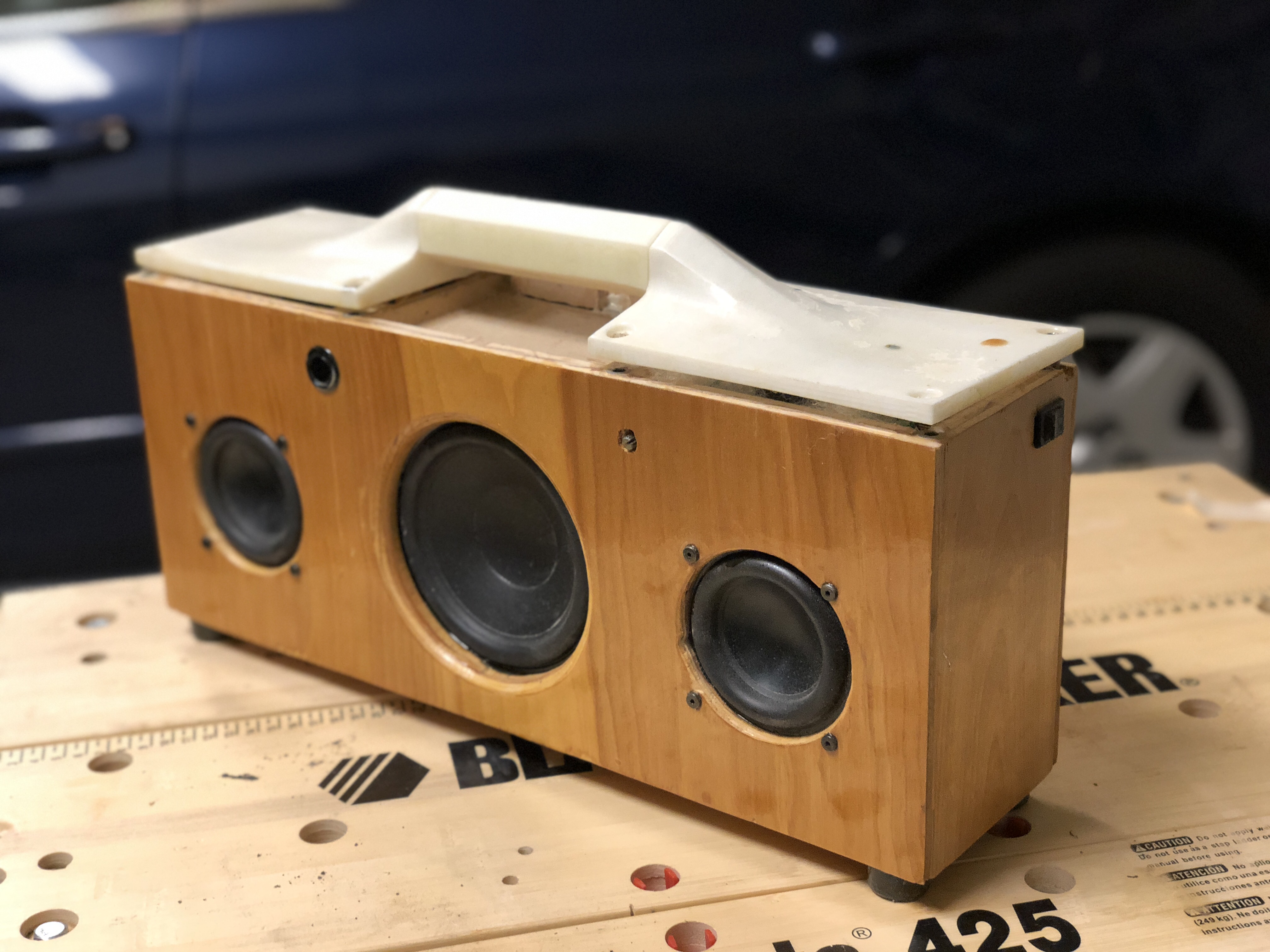
Finished product:

MARRIAGE SOUNDS GOOD

What’s the right wedding gift with 30 days of lead time when your friends are stranded across the Canadian border because of a global pandemic but they’re willing to risk it all for love and get married in a DMZ? I went with an Ikea cutting board. Well—to start.

It turns out that in places where border boundaries are blurred the acoustic offerings are slim. Without loud music (and strong drinks) no party is bompin, and without a bompin party, it’s not a wedding, so there was really only one thing to do: make a matching & linkable set of portable, hi-fidelity bluetooth speakers:

DESIGN SPECS

Cost of parts: $150 (ea.)
Loudness: 96dBSPL, 1m, @ 10% THD, A-weighted
Frequency Response: 50Hz to 20kHz ±5dB (but look at the curves down below)
Connectivity: Bluetooth 5.0
Battery: 3S Lithium-Ion, 37Wh
Runtime: 10 hours at “half volume” input (92dBA output)
Amplifier: 2x50W TPA3116D2 running @ 24V
Difficulty of Build: Dummy high—approx 120hrs from start to finish, requiring 2 CNCs and a 3D printer

In a lot of ways, this was a 2020 capstone project for me: to make something that’s loud, compact, and full of deep bass, with a 30-day conception to finish timeline, I had to pull out at least half of the dirty tricks I’ve learned over the last six years. Here’s how it went down.

ACOUSTIC DESIGN

When it comes to compact loudness with a lot of bass, excursion and efficiency are the belles of the ball, and although I simulated almost every 2-4″ driver I could find, the Dayton ND91-4 drivers (descended from long-gone AuraSound’s Neo-Radial IP) are nearly unbeatable when you factor in magnet strength, Fs, Xmax, price and weight. E.g. Peerless SLS-85S25CP04-04’s (catchy name huh) are potentially 1dB louder for a similar box size but weigh 285% more, while the Fountek FR89EX win for Xmax but need too much back volume and are 2dB less efficient…etc and so on. Just trust me on this one. In a 1.5-2.5 litre box: ND91-4, tuned low.

Tweeters are a fair sight more efficient, so down selection should be mostly driven by crossover frequency, dispersion and ease of integration. The ND91s break up right after 3kHz:

While the ND16/ND20 tweeters are truly amazing, they have to be crossed higher, and they come with a bunch of extra plastic, which clashes with the ultra compact layout I pushed.  LaVoce’s TN100.70 did the trick and can be crossed over at 1.5kHz, which was perfect—the lower a tweeter can be crossed (disclaimer: within its volume displacement limit), the better. Finally, the TN100.70 dispersion is on par with the ND20FA tweeter @ 20kHz (-15dB):

As for the port, in order to maintain compactness and b-b-bass, I had to fit 250mm of port into a 2.5L box while keeping a holdable 4-inch width so I folded it around the ND91 and then crushed the port geometry until it fit in between the driver and borders of the speaker. Tweeter in green, port/body in pink, and woofer in yellow below:

Driving the woofer and tweeter is a 3S 3500mAh battery pack (I use LG 18650s that I order B2B from the factory) paired to a 2x50W Class D TPA3116 D2 amplifier through DC-DC step up converter for maximum power delivery. WONDOM makes a wonderful TPA3116 board with the DSP integrated, which merges with their 3S MPPT Battery Management Board, although to my late-stage chagrin neither of the boards have a step up to power the TPA chipset at an adequate 24V.

BUILD PROCESS

With the acoustic design tucked away 15 days from the deadline, it was time to build. The octagonal outer shell is just a set of 22.5° mitres, tape-clamped, with the patent-pending dual-bevel 8th wall precision cut to match:

The front face was a 2 sided CNC operation, which required calibrating features for aligning the Shaper Origin I used.

Merging the two pieces with the speakers and the front mounted the port was rather easy except for some minor mishaps with a few missing microns; the t-nut I planned to use to rear-mount the woofers were exactly 300 microns short of the planned front face thickness, so after sanding I had two t-nut holes showing on the front face. The port itself had to be printed in 3 pieces because of the complexity of the geometry to fit it both on the border and between the woofer and the back panel:

With space at a premium, but also for aesthetics, I used an LED array for status lights and integrated the on switch into the potentiometer. With that in mind, I also fabbed an ultra slim 6mm bracing/sealing ring for the rear panel mounting, as a butt joint would’ve been ugly but the shell was too thin/weak for threaded inserts. Those loose microns got me again and the flange on the port interfered with the built dimensions of the rear panel, so I slotted that out, but after some truly painstaking finagling of circuit boards, 5 days before the wedding ship date, I was ready for sound test.

That’s when I realized neither the BMS nor the Amp was using a boosted rail which was causing very noticeable voltage clipping, so I had to rip everything open and shove not only a DC-DC buck converter but a giant LC ripple filter (1.3mH L and 100µF C) onto the voltage rail. The only DC-DC buck converters I had in house were straight outta Hua Qiang Bei which means the were both cheap and poorly designed. Buck converters are in general awesome, and about as efficient as one could hope (for 12 to 24V boost, I saw ~85% efficiency depending on load), but the switching causes a lot of load-dependent ripple, which adds both noise and intermodulation into the signal chain. But with that bullet bitten, and with 1 day until ship, it was time to tune. And boy does this design sound good. Sparing the details of the tuning, here’s the final frequency response with a -3dBFS sine sweep @ half input “volume.”

The 2nd harmonic distortion looks pretty high @ 50Hz but this is mostly due to the aggressive non-linear processing I added in for extra kick; a more reasonable measure of THD in this scenario are the 3rd order harmonics, which I kept below 8%. The dips in the mid band (400Hz, 800Hz) are regrettable from a data standpoint (probably due to product baffle dimensions) but overall, these speakers deliver supple bass, smooth vocals, crisp treble, and excellent definition from 50Hz all the way to 20kHz. I added a little bit of level-dependent EQ, so at maximum volume these speakers are loud enough to kick off a backyard party, and at reasonable volumes they deliver a little extra extension for a very full, deep, frequency response. In my book, a thermos-sized speaker that can fill a room down to 50Hz ticks the “bigger than it looks” box; even from another room I found my self saying “damn, these sound good.”

TESSELATION

There are far more than five senses available in the bleak sensorium of human existence, and one of them is the sense that you could’ve done better. Could I have done better? Let’s find out.

Obligatory finished product first:

IMG_3752.JPG

I think the journey began confidently over beers, but the tolerances involved in interpreting what someone means by “portable and loud but doesn’t have to be too loud but also make it look really cool” can allow for a lot of design doubt (by no fault of their own–it’s just hard to gauge what reference points people have for “small” and “loud”), and so by the time I packed the Tesselator out, I had built 6 separate designs, each one but the last dusted in a fine sheen of “not-quite-good-enough.” This is their story (dim the lights).

ROUND 1: TOO BIG

Try 1 was actually pretty awesome. Basically, I wanted to see what the hype was about with the HiVi B4N’s. Ports in small boxes often of chuff me the wrong way and the client wanted “big circles on the front,” which I interpreted to mean speakers. Plus, I go for passive radiators when I can…and so I went for a passive radiator design. I had been having luck with asymmetry, and I wanted to carry a “T” motif through the design.

IMG_2487.JPG

The problem with the B4N’s that all the fanboys won’t admit is there’s an insanely high Q 15 dB break up mode right at 3kHz, and it likes to jump around depending on boundary conditions, air temperature, zodiac sign, etc. [For the uninitiated, basically the B4N is the classic DIY beginner speaker design because it sounds and looks good, is cheap to make, and because so many other people have built it. However, the all metal cone it’s based around tends to “ring” like a bell at annoying frequencies]. So I wanted to be at least 15 dB down by 3kHz which meant a tweeter that could hit 1.5 kHz, and for directivity reasons, I decided on a 500 Hz crossover, which obviously meant I was going to use the Aurasound NS1s.

Then I found a sweet spot of plywood that I could waterfall from top to front face to edge, cut with confidence, laid out some paper circles for test fit, and very poorly lock-mitered the shit out of the wood.

Lock miters as promised:IMG_2498.JPG
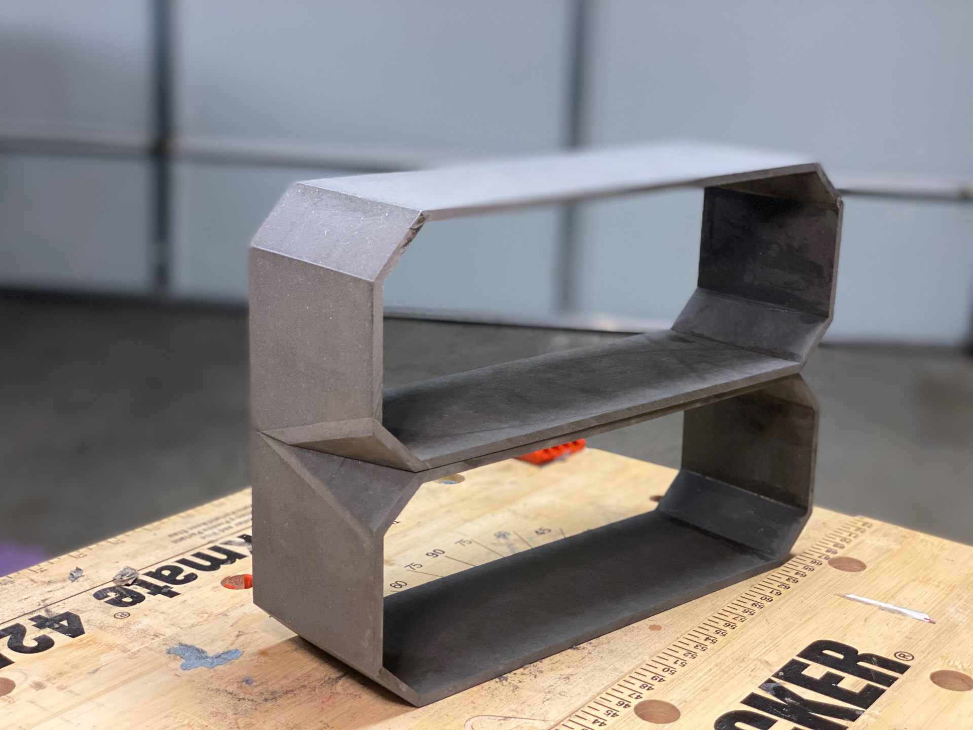
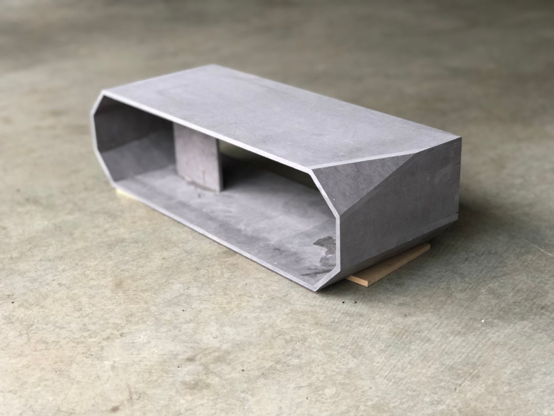
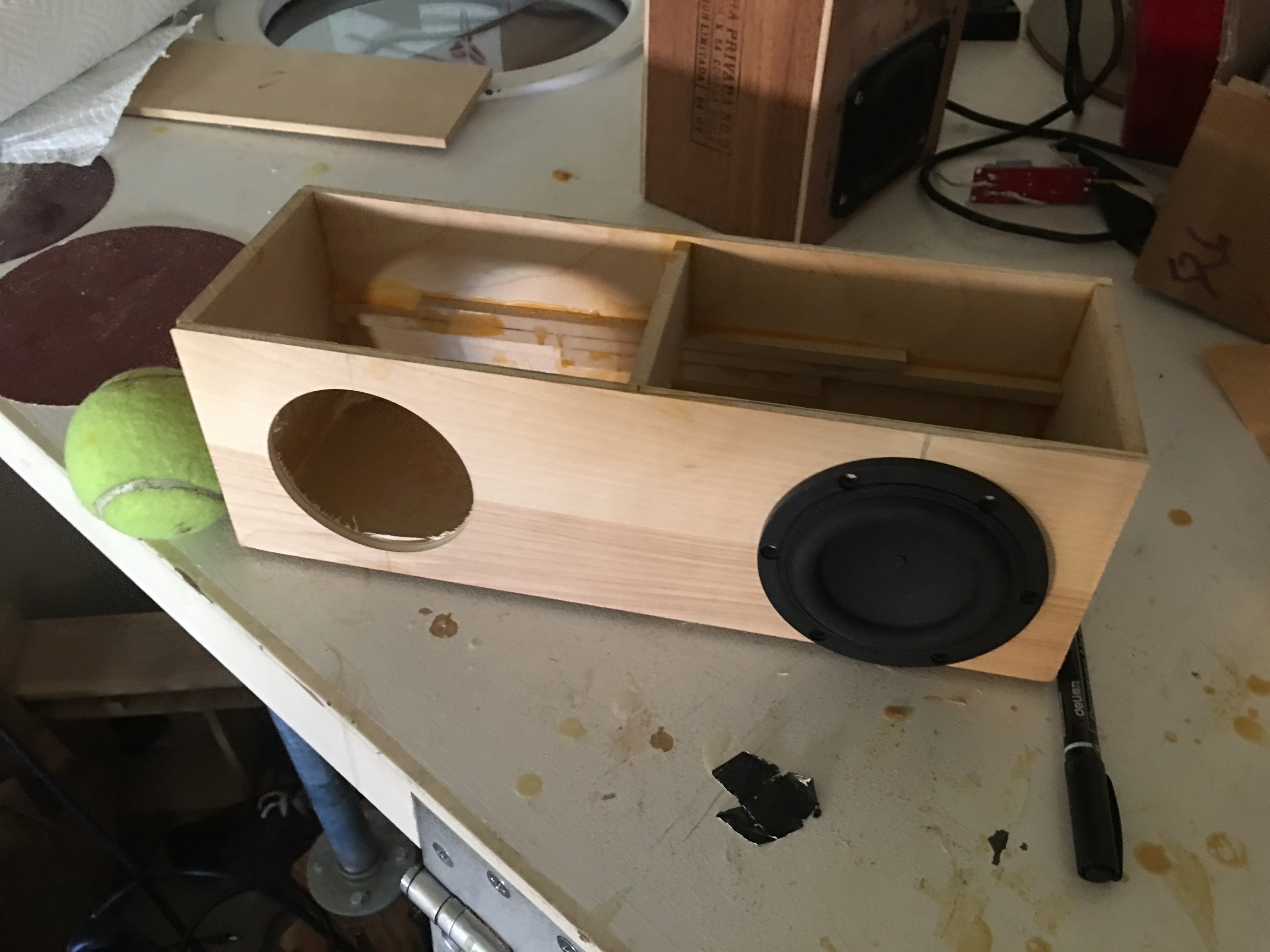
The separated volume is for the electronics–lesson learned from previous projects is when trying to attain a good seal, either get better at electrical engineering, or compartmentalize your bad work.

Of course, I still overestimated my abilities and placed the batteries in the acoustic chamber for space reasons. The white boxes are the enclosures for the NS1s.IMG_2522.JPG

I also had the idiotic notion that using banana plugs as pass-throughs would be simplest, but not only did I get the polarities wrong, it turns out banana plugs are super expensive and take up tons of space:IMG_2503.JPG

I didn’t manage to fuck up the miters too much and the face is perhaps lovable by more than it’s mother:IMG_2947.JPG

I cut out some purple heart and embedded some glow in the dark for the volume knob:

IMG_2690.JPG

With all that shit sorted, it was time to make an absolute mess of the ASP. The signal chain starts with a power-source isolated bluetooth chip, which is split by an op-amp active crossover, the low frequencies going to a china-market bought TDA7492 class D amp and then to the B4N’s while the high frequencies are padded down by potentiometer and sent to a similarly procured TPA3118D2 amp. The TDA7492 is rated for 40W into 8 ohms @ 25V @10% THD, which works reasonably with the B4N’s 25W RMS rating. Typically it’s better to spec an amp with more headroom (@ less THD) over the continuous power rating of a woofer in order to match the crest factor of music, but I didn’t think of that at the time.

IMG_2530.JPG

This is the last build I used analog signal processing on, partially because of the above mess of wires. Here’s the terrible wire management in context:

IMG_3299.JPG

I opted for a glow in the dark,  3D printed, inset handle to preserve the form factor, and then slapped some spar varnish all over that bad boy and called it a day.

IMG_3346.jpg

ROUND 2: TOO QUIET

Sometimes things come together, and sometimes they come together perfectly. This was not either of those scenarios; the “Tesselator” it’s actually just a decent name pun. Honestly, I was pretty happy with Round 1, but it was just not quite there. It was a little too big, and the lock miter bit I used for the edging was one of those cheap amazon finds that reflect their pricing in their quality. So, I started completely anew…by taking an old project that had been called into half-hearted existence with 3 other siblings in a similarly iterative process that finally yielded the Krump Kanon and cutting it in half. In general, this approach is poor.

It sucked for multiple reasons, some of which were that it was ugly and sounded bad and was still too big. Essentially, it failed to meet any of the criteria laid forth.

IMG_8529.jpg

ROUND 3: TOO LITTLE BASS

I then tried a new design that was basically Round 1 but with half the stuff in half the space. It also sucked. I was convinced that it wouldn’t because of my experiential lesson on KK Round 2–“efficiency is king”–but it turns out that only works if you have a pleasing natural response or some good DSP.

It was doubly a shame because the wood that went into the box was beautiful, but for some misguided reason, I used the cheap lock miter bit from Round 1 and, completely to my surprise, it didn’t work well the second time either.

IMG_8530.jpg

ROUND 4: TOO HAMMERED

I then decided that everything I had decided was wrong, that efficiency wasn’t king, and it was all about extension. I went back to some of my “super-compact design” notes and decided to drag some micro-subwoofer Tang Bands into wretched existence. The only problem is that tuning a small box to subwoofer frequencies requires a long-ass tube (because the air spring in a small box is relatively stiff, you need a lot of acoustic mass in the resonating port to get a low resonance frequency), and long-ass ports are very inconvenient to fit into small boxes (not a problem encountered in my daily life). I had a minor stroke of brilliance stroke and decided to make a port that was both a long-ass tube AND a handle, therefore circumnavigating this issue.  Here is the relatively tiny box, which looks shitty because I had also come up with the terrible idea that I’d wrap the whole thing in carbon fiber once assembled:

IMG_2774

And the incredibly sleek and not at all awkwardly protruding port/handle design. IMG_2794

I set the thing up, hit play and was, for the first time in a long time, pleasantly surprised. Here’s a casual video of it in a living room (turn ya sound up and throw on some head phones to appreciate the FIDELITY that’s SPEWING out of this BOOMBOX).

For such a tiny little thing, it was really moving air. It had real potential until I hit it with a hammer.

ROUND 5: TOO UGLY

Not really much to go on about here. It was ugly. I underestimated how weird it would look to have the speakers sticking out of the face instead of flush mounted, and the thing looks like a damn bug-eyed pug.

ROUND 6: NOT BAD

In a surprisingly reflective and narratively satisfying moment, I decided to combine the lessons of the last 5 iterations. I drew up a plan for a small, relatively efficient boombox with precise waterfall miters, inset speakers, DSP, and a port handle. And no fucking carbon fiber.

IMG_3748.JPG

THE DESIGN

On to the even more boring stuff. Yes, yes, I know the stereo image is going to be ruined by placing the “tweeters”  on top of each other. But it looks cool, and there’s no point in attempting to get stereo width out of a box narrower than one’s head.

Anyway, it’s got 2x TB W3-1876 in a mono “sub” configuration, sitting in a 3.7L box stuffed with light polyfill, tuned to 48 Hz with a 12″ long by 1.2″ diameter port. This theoretically gives an f3 of 42 Hz. The port is a 3D printed 3-section design that was epoxied together for surface finish and adhesion. It’s flared on both sides equally for symmetry. The “tweeters” are 1″ W1-1070SH, which are sitting in a 0.1L box and crossed over in a 48 dB/oct LW DSP crossover at 500 Hz. The outer dimensions are approx 4.5″Hx4.5″Dx14″ and the 80Wh battery supplies 24V (nominal) to a China Black Market TDA7492 (to run the woofers) and a CBM TPA3118D2 (for the tweeters) for about 8h of quite listening and 4 hours of TURNT listening  MiniDSP 2×4 runs the tuning, and the bluetooth is run by an APT-X Bluetooth 4.0 chip. The advantages of this chip are high quality transmission with surprisingly low radio noise, but by some trick of China-blackmarket circuitry, it manages to clip it’s output stage at maximum source volumes. I suspect they added a NE5532 output buffer but didn’t manage the gain properly. The numbers on the edge display battery voltage, which is my lazy solution for a battery gauge.

The wood itself is is 1/4″ maple ply, reinforced on the interior with another 1/8″ of ultra-stiff epoxy and some bracing. I finished the wood Water-Lox high gloss finish, which I enjoyed for the simplicity of use and quality of finish. It brings out the grain and luster of the wood beautifully, and it dries quickly into a reasonably durable exterior finish.

THE SUMMARY

Subjectively, the thing is awesome. It sounds far bigger than it looks, and with DSP trickery, there are little concerns of over-excursion despite a relatively low tuning for such small woofers and such a small box. It’s a good feather in the cap for extension over general sensitivity, though it seems that the “high-moving mass, giant coil, really strong magnet” combination that Tang Band is throwing into their designs does a decent job of balancing sensitivity with extension, and this design ends up being a good compromise of the two. The stereo image is shit for previously mentioned issues, but it manages to have pretty laid-back directivity, which is all you could hope for from a small source.

Final assessment: can fill a living room with danceably loud music, yet it is small enough to hand carry to a barbecue. Ship it.

RELEASED INTO THE WILD!


IMG_2730.JPG
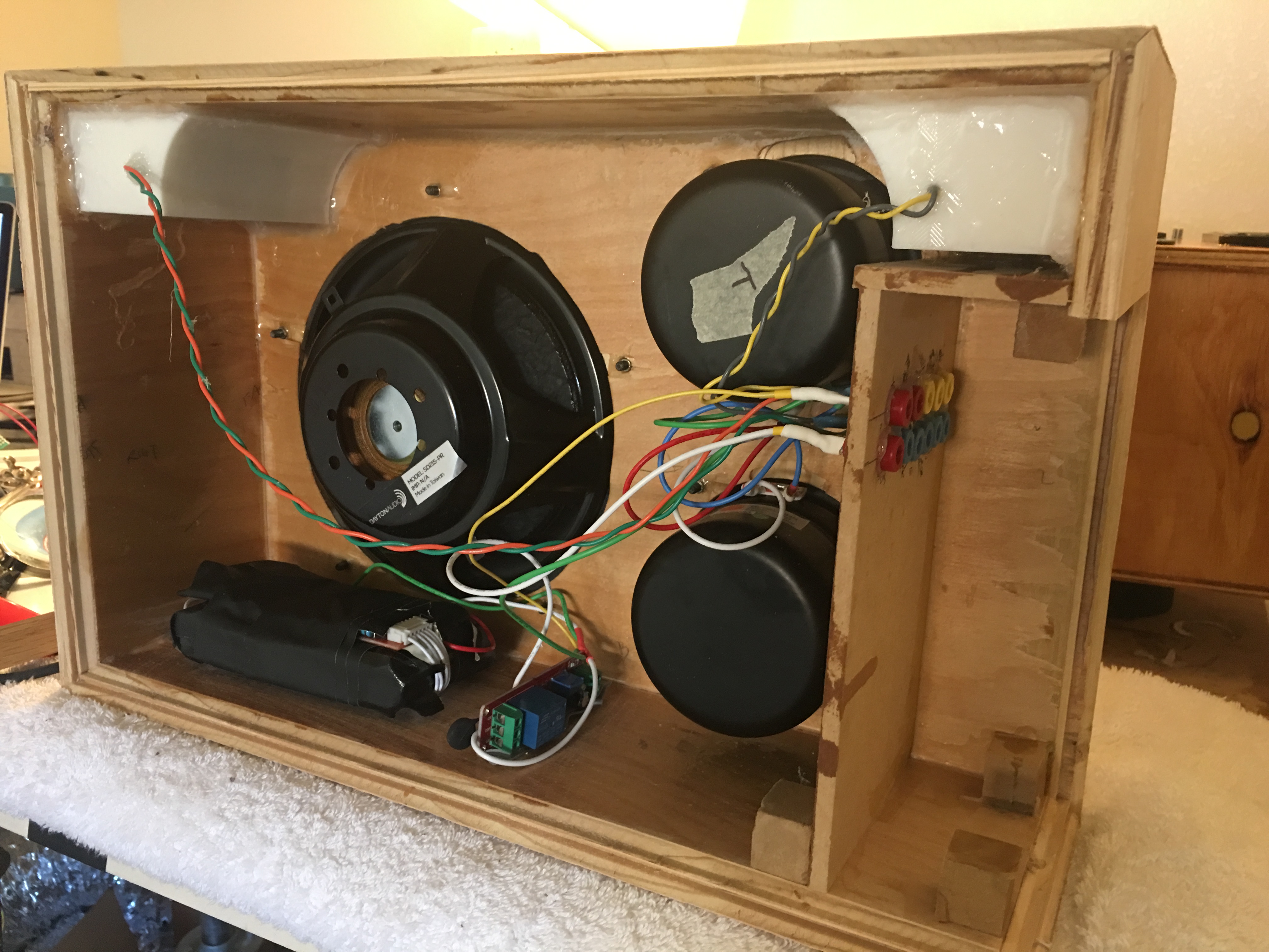
Much like worried parents will fuss over a child before sending them off into the world, I fidgeted over the details of this lil guy, attempting to delay the inevitable departure, filled with pride and worry at the rigors he’ll face out in the real world. Unlike most worried parents, I eventually said “fuck it,” and dropped this fucker off at the local Fedex, to be shipped cross country in a large cardboard box.


The details were particularly sweat-able on this build, as this was essentially the third iteration on the concept, starting with a beast of the beats that went to Keith, and then a semi-pro configuration that went nowhere. Here are the vague details of the build:


img_2203

Obviously, the first detail to isolate is the Lego theme. Legos, by the way, are a fairly mediocre permanent construction material. Turns out the 10-micron precision makes them fairly expensive from a cost/volume stand point (a small enclosure requires a lot of legos). Had my little siblings help me build lego boxes to compare the looks. Turns out rainbow is a crowd favorite

IMG_2208.JPG

Fast forward a few days, after much designing, some deliberation, and then cutting, I’ve got a wood box to match the lego box. I believe I designed for 4L internal volume for each NS3 driver, which, in retrospect, I feel was too much. However, once the wood is cut…alea acta est. I went for a seamless miter approach on this build, to avoid the ugly “end-grain” of the birch plywood. I wrapped the grain around the “depth” of the box, but the grain of the “face” does not flow into the edges. So far I haven’t figured out a solution to this that works out in our boring 3 dimensional Euclidean / Newtonian universe.

IMG_2272.JPG

Here we can see the translucence of the 3d prints, pre assembly. Originally, I had not planned for there to be a VU lightstrip in this build, but then I realized that since I built all the electronics off of the wood box, fitting them into the lego box, which had 5/6 faces constrained already, would be extremely difficult. At this point, I also realized I miscalculated the amount of space wires take up. Medusa rears her ugly cable management head yet again.

IMG_2413.JPG

Now you see what I mean.

IMG_2277.JPG

Analog signal processor demonstrating that I am the particular type of person that loves neat things but does not love making things neat, and so I live in a constant torment of my own devising. I chose a scheme that allows for a bass shelf at lower volumes, but flattens the EQ towards higher volumes—it’s essentially a loudness compensation circuit, except that since I have no reference for the actual loudness of the output (due to lack of information about source gain, listener position). I call it the “party” compensation circuit, because while one might enjoy deep sonorous extension at lower listening levels, once your friends roll through, 14 beers deep each, you’re cranking that fucking volume knob. And while the NS3’s have a lot of allowable excursion before crashing, the garbage bass lines that litter the hip hop soundscape are essentially glorified sine waves that will fuck your shit up. The obvious and simple solution to this is a simple dynamic gain-tied or signal-adaptive high-pass for excursion limiting, or a multi-band compressor. I leave these endeavors as an exercise to the reader until I have the time to implement them on the next build.IMG_2409.JPG

Pre-wood finishing. After disliking the gumminess and amber tint of marine spar varnish, I chose to use tung oil to bring out the figure. Then I sealed the box+3d printed parts with epoxy (bar top) for strength/durability, and finally, for UV protection and hardness, I finished with a clear gloss polycrylic. Here’s what it looks like finished:

IMG_2864.JPG

A BRIEF HISTORY AND MUSINGS ON GRADUATION

Boombox The First

IN the way that most things in life are, there was no moment where the stars aligned and a beam of silver brilliance illuminated me with inspiration; it was not a sudden cataclysm of grand events or even a single moment of clarity. It was more the lucky coincidence of a few small dust mites, just little things, which only in detailed retrospection, could one notice an amount of circumstantial  alignment, that lead to thiswhich, of course, is on par with the scale of endeavor.

I was confronting my post-graduation ennui, as the evaporation of two of the more fulfilling experiences in my life (leading the water polo team, and learning tons of shit with tons of new people) had left me both without purpose and without the satisfaction of achievement of purpose. This was compounded by the fact that I had a degree in Mechanical engineering, which is a certification that I have all the necessary tools to be achieving things, but no job, which rendered those tools somewhat useless. I also other aligned mites; I had a little bundle of cash from graduation, a garage full of random bits of electronics, a shit load of time, and a best friend who wanted portable bluetooth speakers.

So I told him, I could build those for cheaper. He said fuck yeah, and I went to Urban Ore, where a quite lucky mite of dust fell into place; I found a use pair of drivers which just so happened to be the AuraSound NS4-255-4D. If this set of esoteric numbers doesn’t cause heart flutters, the NS4 is one of the best small format full-range drivers in the world, and it’s also impossible to get, because AuraSound was shut down by the feds. Th NS4 some how managed to sneak a little performance past the Iron Law;  it’s loud and it’s got bass in a small box, and it’s cheap (well, used to be cheap; the last commercially-available pair was bought by me, 1.5 years ago for $50). And somehow I had found a pair of these fuckers for $4.

And so I built him a damn boombox, and it’s design was mediocre, and the electrical engineering was shoddy, and the panels were cut from slightly different bits of wood, and nothing was quite lined up right, and it took all summer to get the right parts, and I ran up against the deadline of his birthday so I had to build for 2 days straight, and then it was the day of, and I hadn’t eaten all day because I had to finish it, and I was supposed to be leaving to go his house for a BBQ, and I was late, and I was and had been focusing for the last 8 hours to an extent that makes me wonder about the exact nature of my mental health, and I had my doubts about the whole thing because in someway the little guy’s success was entangled a bit with my own soul, but then it was time to go to his house, and since it was too late to turn back, I turned it on, for the first time, on the porch looking out to the sun setting over the Golden Gate, fog and clouds glowing with orange warmth, with my parents drinking a beer and my little siblings watching, and when the power light flicked on, and the beast was awakened with a bit of thunder, and the peaceful calm of a idyllic Berkeley summer sunset was shattered, I grinned.

Here’s the guy from that exact moment:

bbx1_front.jpg

And Then The Rest

The response was positive, so I built a few more. Though, the first few efforts up until recently were a bit sophomoric, here are a few of them:


Here we’ve got some unfinished pictures of an ultra mini build with a 2 way design using a very surprising 3-inch sub that kicked low-end ass. Built into a (small) cake box.

WP_20150116_20_26_58_Pro

Here’s some beer for scale:WP_20150117_11_02_35_Pro

Here’s the second NS4 build, with some Brazilian cherry I found on the side of the street. Shipped this one to the east coast. Not the most finished product I’ve made but it worked ok.

WP_20141120_017WP_20141119_005

Eventually I realized that the finish (wood pun intended) is as important as the start so I worked on getting a cleaner look and looking into wood varnishes.WP_20150604_21_01_22_Pro

And the most recent piece, the KrumpKanon for Keith “I’ve been lifting so it can be heavy” Savran, complete with Lego detailing, a 200W sub, missile launch switches, and a marine spar varnish. It’s quite heavy.

IMG_2138.JPG

IN BUILDING

So after all that talk of efficiency v extension, I figured I’d actually build something. It worked out that I ended up building on both sides of the coin, as the “Extension” build ended up being pretty gigantic. But the review of both approaches is in and it turns out that in some regards efficiency is more pleasant; I used the Faital Pro 5FE100 in a ~8L enclosure tuned to about 45-50 hz with a 3 inch x 15 inch port which I 3D-printed.  It WOMPS. Sounds great, crisp, powerful. Really pushes the “effortless” bass feeling, until you get below resonance and the woofer starts whacking around. It becomes excursion limited quite fast on songs with a lot of low frequency content, and it sounds pretty alarming. This forces my hand in ASP to put in a high pass around 32Hz-20Hz, adding complexity and heartache. But all in all, not a bad design.

As for the extension, which also sounds good, a different set of issues comes into play. I went with the Tang Band W5-1138SMF ~14L tuned to around 40 hz with a PR, and for starters, the thing is fucking gigantic. Despite the apparent size, 40 hz in 14L is pretty damn good, and it definitely has a presence visually and sonically. It sounds large, powerful, and it’s exceedingly hard to push the woofer itself into distortion. However  pushing the low efficiency of that driver is it’s ridiculous excursion capability, which brings an unexpected issue into play: high excursion means a lot of acceleration. A lot of acceleration mechanically means all kinds of shit is moving around, including things coupled to the boombox through the surface it’s on; put the boombox on the counter and all of a sudden the beer bottles on the counter start wiggling around too. Additionally, in the electrical domain, a lot of acceleration means a lot of voltage, which means more batteries.

These factors push the design to seem a lot less effortless than the 5FE100, potentially because the 1138 design seems to promote higher THD. It’s not necessarily a fair comparison, because the ASP, amp, and battery management on the 5FE100 design happens to be a lot better (I built it second, learned from previous mistakes). Normalizing for those factors, though, the smaller size is pretty great as it turns out that there is usually very little content from 40 Hz and below, and because larger boxes tend to be less efficient in terms of materials.


This slideshow requires JavaScript.

IT HAS BEEN DECIDED

So for  the KrumpKanon I’m going with the W5-1138SMF, and for Keith’s, the W6 version of the same driver. Why? Because it has the excursion, Fs, and general specs to have solid bandwidth and linearity at loud volumes. Unfortunately, if you look at the models:

eliseBoxGrabTB1138VentSpecs_PRChoice2.PNG


The yellow line represents the optimal ported design, while the blue is the optimal 8″ Dayton Audio PR design. The vented design is more efficient, has higher bandwidth, and requires less box volume. However, for a 4″x2.5″ port, opening I’d need 36 inches of port to get the 12L box resonating at 36 Hz. That’s absurd, and what’s more absurd is that at 50W, the airspeed would be ~40 m/s. That’s 90 mph, and the air has to move 90 mph through a folded port 3ft long. I have low expectations for the laminarity of the air flow in that scenario, but an educated guess tells me it would sound like an elephant farting through a muffler.

PR’s it is. With dual 8 inch passive radiators, I could be pretty near the vented design, but a) that’s a ridiculous amount of radiator area for a 5 inch  area, b) that’s 2x the cost, machining, surface area dedicated to the radiator, and c) trying to fit two 8-inch radiators, a 5-inch woofer, and 2 full ranges onto the front of the boom box would be ridiculous. Why not throw them on the back? Well, then the front will look stupid, barren. I want the raw visual and auditory power of a fat fucking 8″ blasting you in the face. But fitting 2 8’s on to the front of a reasonably sized boom box (using the esteemed [boombox name to go here once I find my notes] as a template) would be geometrically dubious.

So at the sacrifice of about 1/3 of an octave of bass, I’m going with a single 8. I hate leaving bass on the table, especially when it’s easy, efficient bass, but given the constraints and my desire for a simplistic design…it’ll have to do. Additionally, and this is the most important part, but, if you look at an analysis of the most popular music being played these days, there’s  little content beneath 40 Hz, and therefore, little need for sound below 40. So I guess 40 Hz it is, and we’ll hope it sounds good. There’s only way to find out.


IT WILL BE DECIDED

After modeling 20+ woofers, including the attractive ScanSpeak classic series, the illustrious semi-pro Morel and FaitalPRO designs, and the uncategorizable SB Acoustic woofers, I’ve decided that there are only two viable designs. For the purpose of listening to  party music in party situations (Keith’s BuffBox), I want something like 104 dB at 48-42Hz at max, solid directivity, and about 3dB head room to handle over-compressed music and power compression that comes with party scenarios. For Elise’s use (KuadKrumpKannon), I’m probably going to want something slightly smaller and with slightly less performance. We can go with 100dB 50-40Hz with 3 dB of head room.

That leaves me with two options, the classic crux, the bane of boomboxes, the designer’s dilemma,  the iron law. For a given size, you can either have more bass but lose sensitivity, or have less bass bandwidth but more loudness. The third unspoken option is get both and pay $$$.

One the one hand, I could go for a 2.1 type set up with the boombox-friendly micro-subwoofer designs like the Tang Band 1138-SMF with it’s extreme 45 Hz free-air resonance, it’s lovely 9.25mm linear x-max, 5-something liter Vas and 82 dB sensitivity. Yeah, it sacrifices sensitivity for low Fs+high xMax at a decent cost point, but with 2^6.3 watts power handling we can potentially get to 99 dB at 1m down to 32 Hz in a 15L cabinet. In my experience, having deep reach with slightly less output can be more enjoyable despite not being as overwhelmingly loud. Essentially, I’d give up loudness for an extra  bass half-octave.

Alternatively, I can go for sensitivity over bandwidth. The FaitalPRO 5FE100 is a great example of this, as it maintains decent excursion and could potentially hit low 50’s in a small box while still being 6 dB more sensitive than the 1138-SMF. In fact, it could  hit 103 dB  in a 8L box, for a 51 Hz-3dB points, or and 40 Hz -3dB in a 15L box. It actually could handle producing about 108 dB (that’s at 100W, it can handle 160W) but above and below the port resonance we’d be we’ll out of the linear excursion range of the woofer. It starts to get directive at 1.5 kHz (beam forming begins at f=c/λ which is 2.7 kHz for a 5 inch woofer), so I could easily cross it over with some equally sensitive 1-2.5 inch speakers around 300 hz and call it a day.  Lots of out put, lots of head room, good package. Only two factors to consider: 1) whether it will work with available  passive radiators and 2) What Would Heathor Trainor Think? About the missing half octave?

On the other hand, I could go for a more sensitive design dual-fullrange or dual woofer tweeter with slightly less reach, but I get 3dB off the bat because I’ll have two woofers. The NS4 would be perfect for this but alas, they are gone from the world. The second best thing is the AuraSound NS3-193-8A , and it’s copy cat brothers: Dayton ND90, ND91, ND105, and DS115 are all great candidates for this. But after modeling I found:

  • AuraSound NS3: Great response, pretty design, 50hz in a 4L box. Play nice with passive radiators. All around solid drivers at a good price. Definitely on the table. The only issue is they’re not that sensitive and they don’t hit super duper hard.
  • ND90: good for this application, but still, lots of ripple. -3dB at 40-38 in 9-7.7 liters. Good news is xMech for days, so bottoming out shouldn’t be an issue for these ND series. Doesn’t work
  • Dayton ND91: great for 1-4 liter enclosures. Looots of ripple otherwise, still a lot of ripple.
  • ND105: lots of ripple, needs at least 14L but can get down to 33 hZ  at -3dB, or in 9L, 38 Hz with a bit of extra efficiency in the pass band.
  • DS115: Kind of a middle ground. In 6 liters, could go to 50 hZ -3dB. They look pretty, and with two of them, I could get 104 dB while staying in the linear region.

The downsides to this approach are: raised complexity (I’ll have to fit 2 4th order systems in the same form factor), limited design flexibility (long ports are almost out of the question and passive radiators are harder to fit), potentially greater cost, and of course, half the space which usually ends up meaning less bass.

Here is a graphical explanation of all that jazz ^.

TF ELise session

Transfer Function of Speaker. -3dB point marked in red.

But what do the colors mean? See next photo.

20w legend

Legend of which colors match up with with speaker/box designs.

Transfer functions are great but we want to know the absolute level.

20W comparison

Absolute level. Compare the sensitivity vs the bandwidth of the various drivers. The ND105 manages to be a good combination of both.

But how loud do they really get with linear excursion constraints?

maxSPL Elise session

Maximum (linear excursion) loudness. Note the FaitalPROs (magenta, green, teal) manages massive power handling until the excursion limit kicks in. The previously impressive ND105 (orange) has little-to-no advantage over the 1138SMF (yellow) due to its lower power handling and limited excursion.

So…what to do?